Common-mode voltage suppression method and system for unbalanced npc three-level inverter on DC side

A three-level inverter and common-mode voltage technology, which is applied in the direction of converting AC power input to DC power output, electrical components, output power conversion devices, etc., can solve the problems of slow modulation efficiency, poor suppression of common-mode voltage, Problems such as slow dynamic response speed, to achieve fast dynamic response speed, common mode voltage suppression, and elimination of even harmonics

Active Publication Date: 2020-04-21
SHANDONG UNIV
View PDF6 Cites 0 Cited by
  • Summary
  • Abstract
  • Description
  • Claims
  • Application Information

AI Technical Summary

Problems solved by technology

[0004] The inventor found that the existing common-mode voltage suppression method is mainly aimed at the situation where the voltages of the two capacitors on the DC side of the NPC three-level inverter are equal, that is, the situation where the midpoint potential is balanced
In the high-voltage and high-power electric drive system, the DC side of the NPC three-level inverter system usually uses two sets of independent diode uncontrolled rectification circuits. At this time, the voltages of the two capacitors on the DC side will be unequal. The traditional PI control method, the dynamic response speed of the two capacitor voltages on the DC side is slow; the traditional three-phase modulation method needs to change the triangular carrier in real time, which makes the modulation efficiency slow and the effect of suppressing the common mode voltage is poor

Method used


Image

  • Common-mode voltage suppression method and system for unbalanced npc three-level inverter on DC side
  • Common-mode voltage suppression method and system for unbalanced npc three-level inverter on DC side
  • Common-mode voltage suppression method and system for unbalanced npc three-level inverter on DC side

Examples


Embodiment 1

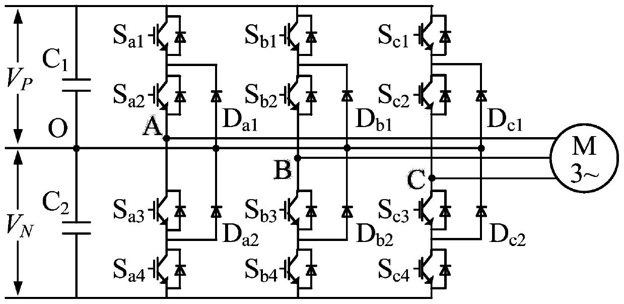
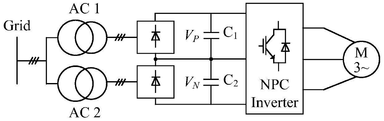
[0053] figure 2It shows that the front ends of the two capacitors on the DC side of the NPC three-level inverter are respectively connected to a group of diode uncontrolled rectifiers. At this time, the voltages of the two capacitors will be unequal. In order to suppress the common mode voltage in the case of unbalanced capacitor voltage on the DC side, and at the same time ensure low harmonic three-phase output current.

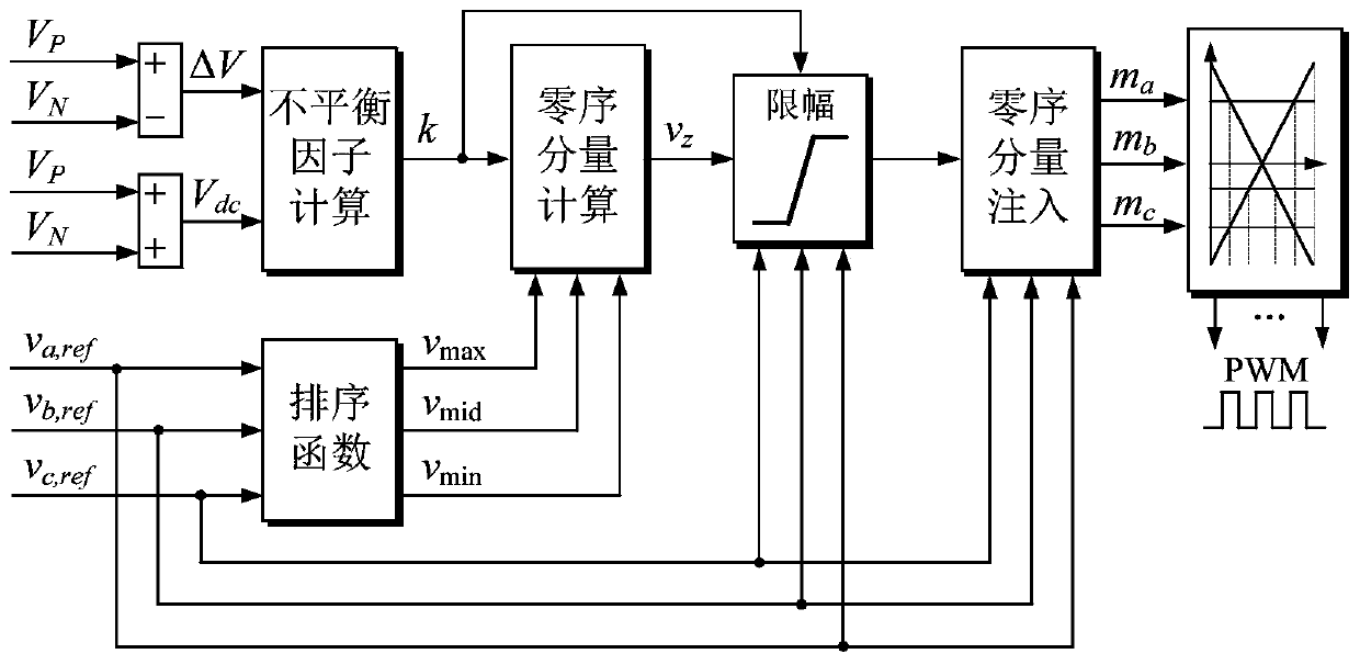
[0054] The zero-sequence component expression of Embodiment 1 is

[0055]

[0056] In order to avoid the basic voltage vector of high common-mode voltage amplitude caused by over-modulation causing output waveform distortion and carrier modulation, it is necessary to zero-sequence component v of the first embodiment z clipping

[0057] max{v za,min ,v zb,min ,v zc,min}≤v z ≤min{v za,max ,v zb,max ,v zc,max}(8)

[0058] in,

[0059]

[0060]

[0061] j = a, b, c.

[0062] The zero-sequence component v z1 Inject a three-phase modulating ...

Embodiment 2

[0070] Figure 6 It is shown that the front ends of the two capacitors on the DC side of the NPC three-level inverter are connected to a group of diode uncontrolled rectifiers. At this time, according to the requirements of the actual system, the voltage difference between the two capacitors can be equal to its corresponding voltage by means of control. Desired point.

[0071] Let the given value of the voltage difference between the two capacitors on the DC side be Δv ref , design the deadbeat midpoint potential control algorithm, and get the given value of the midpoint current

[0072]

[0073] In the case of unbalanced DC side, the expression of the midpoint current of the NPC three-level inverter system is

[0074]

[0075] Among them, n j is the switch state transition function of phase j (j=a,b,c) of the NPC three-level inverter system, defined as

[0076]

[0077] In order to realize that the voltage difference between the two capacitors is equal to its cor...

Embodiment 3

[0098] This embodiment provides a computer-readable storage medium, on which a computer program is stored, and when the program is executed by a processor, the DC-side unbalanced NPC three-level inverter as described in Embodiment 1 or Embodiment 2 is realized. steps in the common-mode voltage rejection method.


PUM


Abstract

The present disclosure provides a common-mode voltage suppression method and system for an unbalanced NPC three-level inverter on the DC side. Among them, the common-mode voltage suppression method includes: in the case of an unbalanced capacitor voltage on the DC side of the NPC three-level inverter, according to the two capacitor voltages on the DC side and the three-phase modulation wave, calculate the zero-sequence component and perform amplitude limiting processing; The zero-sequence component is injected into the three-phase modulation wave, and the PWM driving signal is generated after modulation by two sets of triangular carrier waves with a phase difference of 180 degrees.

Description

technical field [0001] The disclosure belongs to the field of power electronics, and in particular relates to a common-mode voltage suppression method and system for an unbalanced NPC three-level inverter on the DC side. Background technique [0002] The statements in this section merely provide background information related to the present disclosure and do not necessarily constitute prior art. [0003] Since it was proposed in the 1980s, the diode-clamped (Neutral-point clamped, NPC) three-level inverter has been widely used in the fields of photovoltaic power generation, comprehensive management of power quality, and high-power electric drive. This topology has significant advantages such as low voltage stress of the power switch tube, good output waveform quality, and low total harmonic distortion rate. The common mode voltage is generated by the switching action of the power switch tube in the inverter circuit. In the high-power electric transmission system, the commo...

Claims


Application Information

Patent Timeline
Patent Type & Authority Patents(China)
IPC IPC(8): H02M7/487H02M1/12H02M1/44
CPCH02M1/12H02M1/44H02M7/487H02M1/123
Inventor 张承慧秦昌伟邢相洋李晓艳
Owner SHANDONG UNIV
Why Eureka
Try Eureka