SNCR denitrification system and denitrification method

A technology of denitrification and denitrification agent, applied in the direction of separation method, chemical instrument and method, lighting and heating equipment, etc., can solve the problems of high ammonia escape, high operating cost, low NOx removal efficiency, etc., and achieve improved contact area, vaporization Good effect, the effect of increasing the flow rate

Inactive Publication Date: 2019-07-12
贾新华
View PDF11 Cites 4 Cited by
  • Summary
  • Abstract
  • Description
  • Claims
  • Application Information

AI Technical Summary

Problems solved by technology

SCR (Selective Catalytic Reduction) uses a catalyst and has high efficiency, but the operating cost is high due to the need to update the catalyst
The reason why SNCR and SCR are often used in combination is mainly due to the low NOx removal efficiency of SNCR and the high ammonia slip

Method used


Image

  • SNCR denitrification system and denitrification method
  • SNCR denitrification system and denitrification method
  • SNCR denitrification system and denitrification method

Examples


Embodiment 1

[0042] Example 1: 2×130t / h circulating fluidized bed boiler denitrification project of a chemical company.

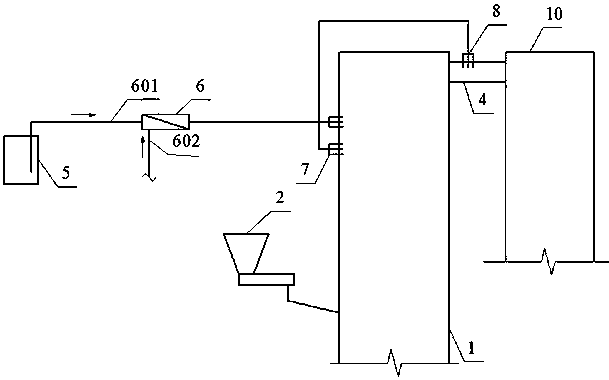
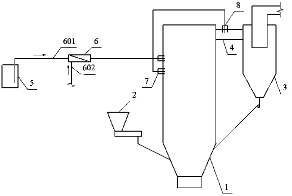
[0043] Furnace flue gas volume is 340000Nm 3 / h, the original NOx emission concentration is 300~350 mg / Nm 3 . The mixed ammonia vapor enters the boiler through the nozzle group, and the nozzle group is arranged in 4 groups, of which two groups are arranged on the flue before the cyclone inlet, and the other two groups are arranged in the middle of the furnace, near the return point. NOx emission concentration dropped to 30mg / Nm 3 the following. The denitrification rate reaches 90%,

example 2

[0044] Example 2: A chemical company's 2×35t / h circulating fluidized bed boiler denitrification project.

[0045] Single boiler flue gas volume 50000 Nm 3 / h. NOx original emission concentration 450~480 mg / Nm 3 . The mixed ammonia vapor enters the boiler through the nozzle group, and the nozzle group is arranged in 2 groups, which are arranged at the lower part of the secondary air inlet of the side wall of the boiler. NOx emission concentration dropped to 30mg / Nm 3 the following. The denitrification rate is over 90%.


PUM

PropertyMeasurementUnit
denitrification rateaaaaaaaaaa

Abstract

The invention discloses an SNCR denitrification system and a denitrification method. The SNCR denitrification system comprises a first nozzle group arranged in the middle-upper part of a furnace hearth and/or a second nozzle group arranged on the connection flue, and an ammonia liquid tank and a mixing vaporizer. The mixing vaporizer comprises an ammonia liquid pipe, a steam pipe, a venturi mixingpipe and a vaporizing pipe. A three-way structure is formed between the ammonia liquid pipe, the steam pipe and the vaporizing pipe. The nozzle adopts a sleeve structure, including a denitrifying agent inner tube and a cooling sleeve, and the front end of the denitrifying agent inner tube is provided with a venturi atomizing tube and a nozzle is arranged at the outlet end of the venturi atomizingtube. A steam with pressure is introduced into the mixing vaporizer through a steam pipe, and a negative pressure is formed when that steam passes through the venturi vaporization pipe, so that a denitrifying agent in the ammonia liquid tank is sucked into the venturi vaporization pipe from the ammonia liquid pipe under the negative pressure; the denitrifying agent and steam are mixed and heat isexchanged in the venturi vaporizing pipe, so that the denitrifying agent is vaporized. The denitrifying agent steam is sent from the vaporizing pipe to the spray pipe and sprayed into the flue gas toremove NOx from the flue gas. The invention has the advantages of good ammonia liquid mixing and atomizing effect, high denitrification efficiency and the like.

Description

technical field [0001] The invention relates to an efficient SNCR denitration system and a denitration method, belonging to the technical field of combustion flue gas treatment. Background technique [0002] Nitrogen oxides (NOx) are one of the main pollutants in the atmosphere. In my country, fossil fuels account for a high proportion of primary energy consumption. As the public's awareness of environmental protection increases, the requirements for NOx emissions in flue gas are becoming more and more stringent. In order to meet the increasingly stringent emission standards, most coal-fired flue gas denitrification adopts SNCR-SCR combined denitrification system. SNCR (Selective Non-Catalytic Reduction) does not use a catalyst, which can save investment to a certain extent, but it needs to be set in the high temperature section. SCR (Selective Catalytic Reduction) uses a catalyst and has high efficiency, but the operating cost is high due to the need to update the cataly...

Claims


Application Information

Patent Timeline
Patent Type & Authority Applications(China)
IPC IPC(8): B01D53/78B01D53/56F23J15/02
CPCB01D53/56B01D2251/2062B01D2251/2067B01D2258/0283B01D2259/124F23J15/003F23J15/02
Inventor 贾新华
Owner 贾新华
Why Eureka
Try Eureka