Tensioner shaft pin bending device and bending method

A technology of bending device and tensioner, which is applied in the field of tensioner production, can solve the problems of high labor cost, low efficiency, and high labor intensity, and achieve the effects of low labor cost, high degree of automation, and reduced labor intensity

Pending Publication Date: 2019-07-12
MAANSHAN HUINENG ELECTRONICS
View PDF11 Cites 0 Cited by
  • Summary
  • Abstract
  • Description
  • Claims
  • Application Information

AI Technical Summary

Problems solved by technology

[0006] Aiming at the problems of low efficiency, high labor intensity and high labor cost in the production mode of manually bending tensioner shaft pins in the prior art, the present invention provides a tensioner shaft pin bending device and bending method, through The adjustment device, the clamping device and the bending pin device are set up in coordination, and coordinate with each other according to the processing sequence of adjusting the direction of the shaft pin→locking the ratchet shaft→bending the shaft pin to complete the automatic bending of the shaft pin on the tensioner. High degree of automation and production efficiency, low labor intensity and labor cost, and high consistency of the tensioner produced

Method used


Image

  • Tensioner shaft pin bending device and bending method
  • Tensioner shaft pin bending device and bending method
  • Tensioner shaft pin bending device and bending method

Examples


Embodiment 1

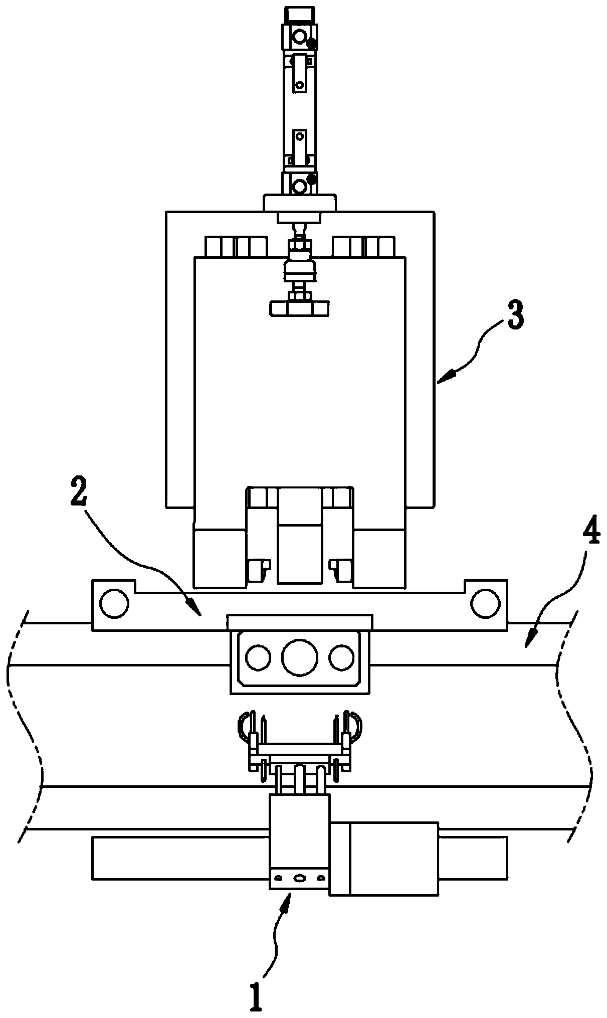
[0070] A tensioner shaft pin bending device, such as figure 1 , 8 As shown, it includes an adjusting device 1 , a clamping device 2 and a bent pin device 3 which are arranged in cooperation with each other. Such as figure 1 As shown, the conveying line 4 extends horizontally, and the adjustment device 1, the clamping device 2 and the bending pin device 3 are arranged longitudinally on the shaft pin bending station on the conveying line 4, and the adjusting device 1 is arranged on the conveying One side of the line 4 , the bending pin device 3 is arranged on the other side of the conveying line 4 , and the clamping device 2 is arranged above the conveying line 4 .

[0071] The state before the shaft pin 5 on the tensioner described in this embodiment is bent is as follows: Figure 10 As shown in , it has a bent end 51 and a straight end 52, when assembling the shaft pin 5 as Figure 9 As shown in , insert its straight end 52 down vertically into the pin holes at both ends o...

Embodiment 2

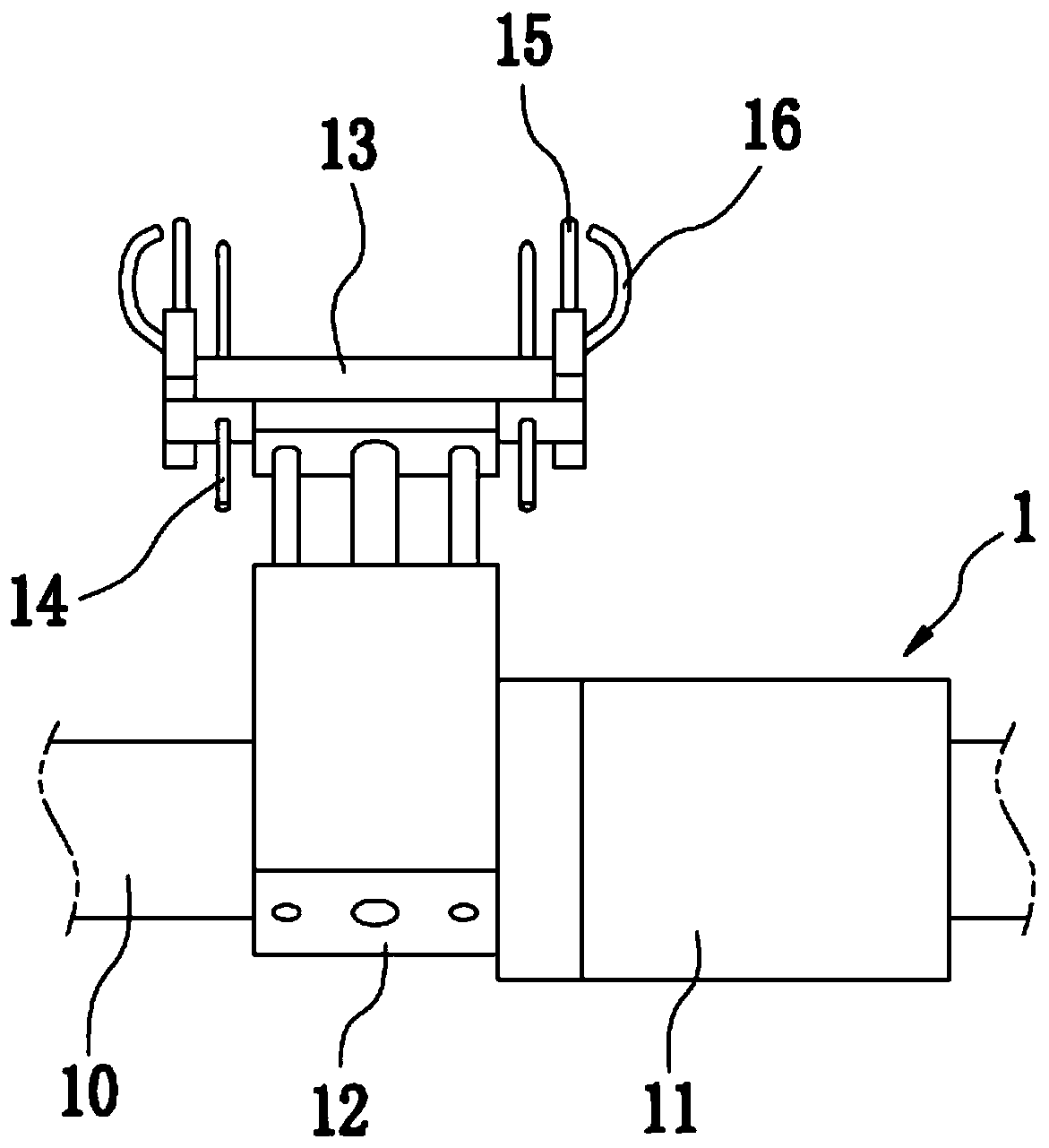
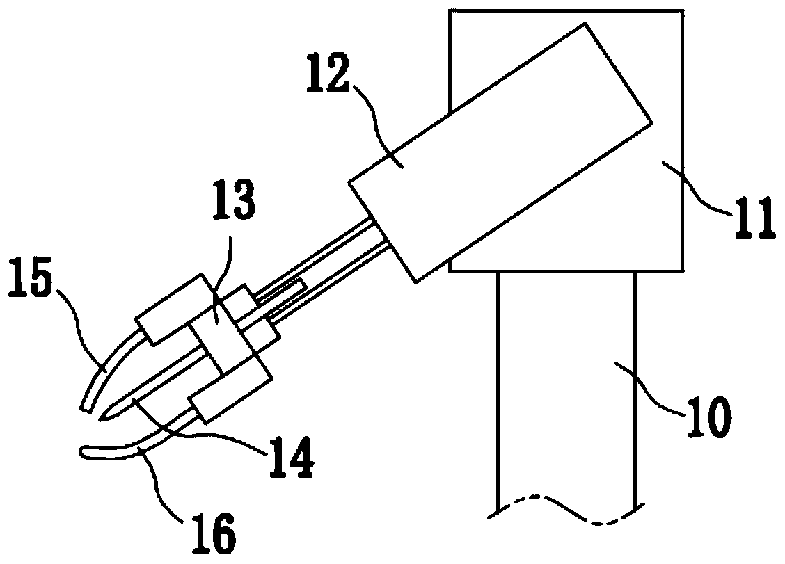
[0075] The pin bending device of the tensioner in this embodiment, on the basis of the first embodiment, provides a specific structure of the adjusting device 1 . Such as figure 2 , 3 As shown, the adjustment device 1 includes a cylinder one 12, a needle seat 13, an upper air pipe 15 and a lower air pipe 16; a vertical plate 10 is vertically fixed on one side of the conveying line 4, and a mounting seat one 11 is fixed on the upper end of the vertical plate 10 ;Such as figure 2 As shown in , the cylinder one 12 is obliquely fixed on the left side of the mounting base one 11; the needle seat 13 is fixed on the end of the piston rod of the cylinder one 12; the upper air pipe 15 and the lower The trachea 16 is respectively fixed on the upper and lower sides of the needle holder 13; the upper trachea 15 and the lower trachea 16 can blow out the airflow, and the flow of the airflow can be controlled. Specifically, the upper trachea 15 and the lower trachea 16 adopt The metal c...

Embodiment 3

[0082] The pin bending device of the tensioner in this embodiment, on the basis of Embodiments 1 and 2, provides a specific structure of the clamping device 2 . Such as Figure 4 , 5 As shown, the clamping device 2 includes a cylinder two 22 and a mechanical claw 23; a support 20 is vertically fixed on one side of the conveying line 4, and the support 20 includes two vertically arranged columns and a horizontally arranged upper end of the column. The crossbeam 200, the front side of the crossbeam 200 extends to the top of the conveying line 4, the middle part of the upper side of the crossbeam 200 is fixed with the mounting seat 21, and the piston rod of the cylinder 222 is vertically fixed on the mounting seat 2 downwards. The front side of 21; said mechanical claw 23 claws are vertically fixed on the piston rod end of said cylinder two 22 downward; said mechanical claw 23 is a pneumatic mechanical claw.

[0083] After the shaft pin 5 rotates in place, control the action of...


PUM


Abstract

The invention discloses a tensioner shaft pin bending device and bending method, and relates to the technical field of tensioner production. The device comprises an adjusting device arranged on one side of a conveying line, and used for adjusting the bending end of a shaft pin on a tensioner to the side pointing to the position where a pin bending device body is located, a clamping device and thepin bending device body; the clamping device is matched with the adjusting device in the direction perpendicular to the conveying line, and is arranged above the conveying line and used for clamping two ends of a ratchet shaft on the tensioner, and the pin bending device body is matched with the adjusting device and the clamping device in the direction perpendicular to the conveying line and is arranged on the other side of the conveying line and used for applying force to the straight end of the shaft pin to bend the straight end. The adjusting device, the clamping device and the pin bendingdevice body are matched in a coordinated manner according to the machining sequence of shaft pin direction adjusting, ratchet shaft locking and shaft pin bending, automatic bending of the shaft pin onthe tensioner is finished, the automation degree and the production efficiency are high, labor intensity and manpower cost are low, and the produced tensioner is high in consistency.

Description

technical field [0001] The invention relates to the technical field of tensioner production, in particular to a bending device and a bending method for a shaft pin of a tensioner. Background technique [0002] During the transportation of goods, it is often necessary to bind them tightly with straps to prevent the goods from bumping and falling during transportation. The ratchet tensioner is a common auxiliary strapping tool for strapping, which can help people carry out cargo quickly and efficiently. Reliable binding and fastening, and has the advantages of large binding force and labor-saving operation. Most of its structures include trigger arm, support arm, ratchet, belt fixed shaft, ratchet shaft, clips, stoppers, etc. The ratchets on both sides are connected by the ratchet shaft and act synchronously. When the clip and the stopper are both engaged on the teeth of the ratchet, the pulling arm moves back and forth continuously relative to the support arm, which can drive...

Claims


Application Information

Patent Timeline
Patent Type & Authority Applications(China)
IPC IPC(8): B21D7/00B21D7/16
CPCB21D7/00B21D7/16
Inventor 苏山山
Owner MAANSHAN HUINENG ELECTRONICS
Why Eureka
Try Eureka