Lateral load application device and lateral load application method for ERW pipe

An application device, tube side technology, applied in the direction of metal processing equipment, resistance welding equipment, welding equipment, etc., to improve welding quality, avoid cold welding and over-burning, and achieve the effect of uniform temperature distribution

Active Publication Date: 2019-07-12
徐州博创建设发展集团有限公司
View PDF10 Cites 2 Cited by
  • Summary
  • Abstract
  • Description
  • Claims
  • Application Information

AI Technical Summary

Problems solved by technology

[0003] In order to overcome the deficiencies of the above-mentioned prior art, the present invention provides an ERW pipe lateral load application device that can realize uniform temperature distribution in the thickness direction of the weld seam of the pipe blank, so as to realize the outer surface, inner surface and The temperature at the center of the thickness is equal, thereby avoiding defects such as cold welding and over-burning caused by uneven temperature distribution, and improving the welding quality of the tube blank weld seam

Method used


Image

  • Lateral load application device and lateral load application method for ERW pipe
  • Lateral load application device and lateral load application method for ERW pipe
  • Lateral load application device and lateral load application method for ERW pipe

Examples


Embodiment Construction

[0030] The present invention will be further described below in conjunction with the accompanying drawings and embodiments.

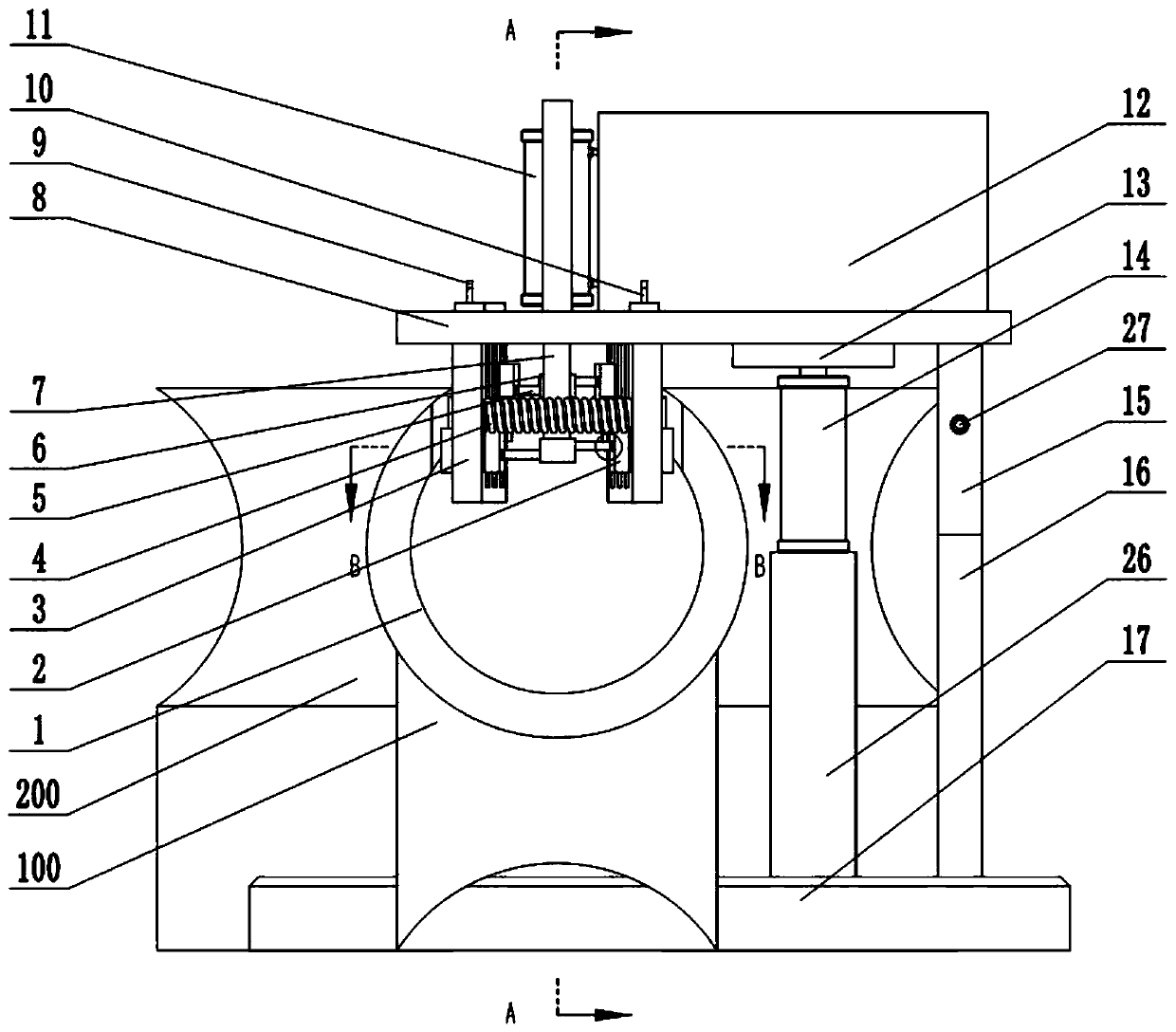
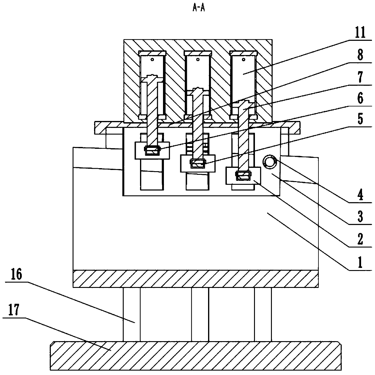
[0031] Such as figure 1 As shown, the ERW pipe lateral load applying device of the present invention includes an electrode block 2, an electrode panel 3, a pressure spring 4, an electrode connecting rod 5, a workbench 8, a telescoping mechanism, a support plate 13, a lifting device, a base 17 and a conductive plate twenty two. The telescopic mechanism includes an electrode hydraulic cylinder 11 , a hydraulic pump 12 and a hydraulic rod 7 , and the lifting device includes a platform hydraulic cylinder 14 , a chute member 15 , a fixed bracket 16 and a column 26 .

[0032] Such as figure 1 As shown, the workbench 8 is supported by a lifting device capable of adjusting its height. The lifting device includes three columns. The first column is fixed between the base 17 and the workbench 8. The first column includes a platform hydraulic cylinder 14 and a co...


PUM


Abstract

The invention discloses a lateral load application device for an ERW pipe. The lateral load application device for the ERW pipe comprises electrode blocks, electrode panels, a pressure spring, an electrode connection rod, a workbench, a telescoping mechanism, a support plate, a lifting device, a base and a conductive plate, wherein under the pressure effect of the pressure spring, the electrode blocks in the electrode panels cling to the side surface of a pipe blank. The invention further provides a lateral load application method for the ERW pipe. A hydraulic rod on an electrode hydraulic cylinder is fixed to a connection rod sleeve, and the two electrode plates at corresponding positions on the electrode panels at the two sides can be driven simultaneously, so that the problem that the two electrode blocks are asymmetric with respect to a welding joint is solved; a high-frequency current is loaded onto the side surface of the pipe blank, uniform temperature distribution of the welding joint of the pipe blank in a wall thickness direction is realized by properly adjusting the relative positions of the electrode blocks on the side surface of the pipe blank, and then the defects ofcold welding, overburning and the like which are brought by non-uniform temperature distribution is avoided, and the quality of the welding joint of the pipe blank is improved.

Description

technical field [0001] The invention relates to the field of high-frequency resistance welded pipes, in particular to an ERW pipe lateral load application device and a lateral load application method thereof. Background technique [0002] ERW pipe is a kind of electric resistance welded pipe. The basic principle of welding is high-frequency current skin effect and proximity effect. High-frequency current is used to generate resistance heat of induced current to heat and melt the welding edge of the tube billet, and then extrusion is completed. welded. The advantages of ERW pipe welding are fast heating, high production efficiency, and because the weld seam is formed by melting the base material of the steel strip body, no foreign filler metal is required. Therefore, the application of this welding process is becoming more and more extensive. However, existing studies have found that for the conventional heating method in which the electrodes are placed on both sides of the ...

Claims


Application Information

Patent Timeline
Patent Type & Authority Applications(China)
IPC IPC(8): B23K11/00B23K11/36
CPCB23K11/00B23K11/36
Inventor 于恩林牛身身
Owner 徐州博创建设发展集团有限公司
Why Eureka
Try Eureka