
Glass processing center

A processing center and glass technology, applied in stone processing tools, metal processing equipment, stone processing equipment, etc., can solve the problems of potential safety hazards and low tool change efficiency, and achieve high tool change efficiency and safe and convenient operation.

Pending Publication Date: 2019-07-12
SHENZHEN CREATE CENTURY MACHINERY
View PDF0 Cites 2 Cited by
  • Summary
  • Abstract
  • Description
  • Claims
  • Application Information

AI Technical Summary

Problems solved by technology

Among 3C products, the current market demand for glass is greater. In order to make the glass surface meet the requirements of smoothness, the existing technology uses a combination of rough grinding and fine milling. Since this process involves many types of tools, CNC glass processing centers capable of rough grinding and fine milling usually do not include a tool magazine, and the tool change operation is generally performed manually, which not only poses safety hazards, but also has low tool change efficiency

Method used


Image

  • Glass processing center
  • Glass processing center
  • Glass processing center

Examples


Embodiment Construction

[0022] The technical solutions in the present invention will be clearly and completely described below in conjunction with the drawings in the embodiments of the present invention.

[0023] It should be noted that all directional indications (such as up, down, left, right, front, back...) in the embodiments of the present invention are only used to explain the relationship between the components in a certain posture (as shown in the accompanying drawings). Relative positional relationship, movement conditions, etc., if the specific posture changes, the directional indication will also change accordingly.

[0024] In addition, the descriptions involving "first", "second" and so on in the present invention are only for descriptive purposes, and should not be understood as indicating or implying their relative importance or implicitly indicating the quantity of the indicated technical features. Thus, the features defined as "first" and "second" may explicitly or implicitly includ...


PUM


Abstract

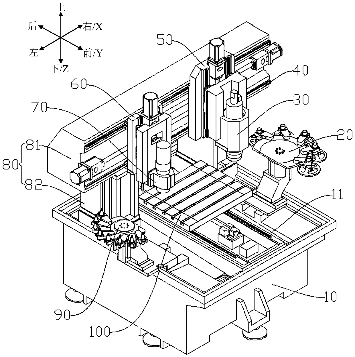
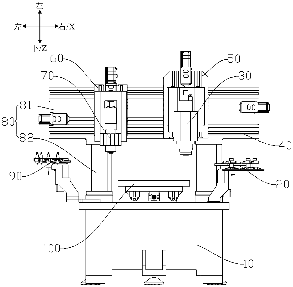
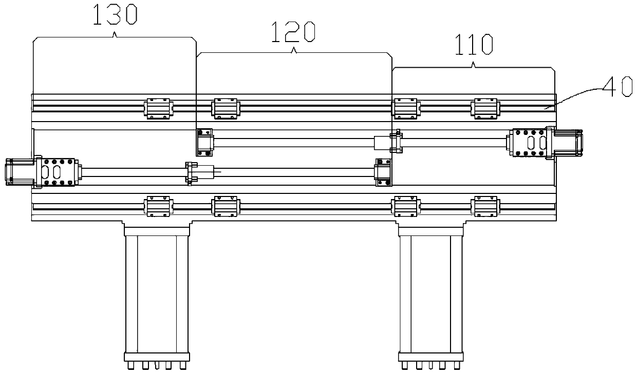
The invention provides a glass processing center. The glass processing center comprises a base, a workbench, a portal frame, an X1 sliding plate, an X2 sliding plate, a first tool changer, a second tool changer, a first main shaft assembly and a second main shaft assembly, wherein a Y-axis guide rail is arranged on the base, the workbench is arranged on the Y-axis guide rail in a sliding mode, theportal frame is arranged on the base and is provided with an X-axis guide rail, the X1 sliding plate is arranged on the X-axis guide rail in the sliding mode and is provided with a Z1-axis guide rail, the X2 sliding plate is provided with a Z2-axis guide rail, the first tool changer and the second tool changer are respectively arranged on both sides of the Y-axis guide rail on the base, the firsttool changer is used for storing roughing tools, the second tool changer is used for storing finishing tools, the first main shaft assembly is arranged on the Z1-axis guide rail in the sliding mode and corresponds to the first tool changer, tool change can be performed on the first tool changer for rough machining, the second main shaft assembly is arranged on the Z2-axis guide rail in the sliding mode and corresponds to the second tool changer, and tool change can be performed on the second tool changer for finish machining. Quick automatic tool change of the two main shaft assemblies can beperformed on the corresponding tool changers, the operation is safe and convenient, and the tool change efficiency is high.

Description

technical field [0001] The invention relates to the technical field of numerically controlled glass processing centers, in particular to a glass processing center. Background technique [0002] 3C products (Computer, Communication and Consumer Electronics) are being updated rapidly, and the market demand is increasing rapidly. Among 3C products, the current market demand for glass is greater. In order to make the glass surface meet the requirements of smoothness, the existing technology uses a combination of rough grinding and fine milling. Since this process involves many types of tools, CNC glass processing centers capable of rough grinding and fine milling usually do not include a tool magazine, and the tool change operation is generally performed manually, which not only poses safety hazards, but also has low tool change efficiency. Contents of the invention [0003] Based on this, it is necessary to provide a glass processing center with safe tool changing operation ...

Claims


Application Information

Patent Timeline
IPC IPC(8): B28D1/00B28D1/18B28D7/00B24B19/22B24B27/00
CPCB28D1/003B28D7/005B28D1/18B28D7/00B24B19/22B24B27/0076
Inventor 陈作驰
Owner SHENZHEN CREATE CENTURY MACHINERY
Learn More