Method for blocking pneumatic discharging valve

A kind of unloading valve, pneumatic technology, applied in the direction of valve operation/release device, lifting valve, furnace charge, etc., can solve the problems such as difficult to control, inconvenient control, safety accidents, etc., to achieve easy maintenance control, the length of the skylight minimized effect

Inactive Publication Date: 2019-07-12
杨佳志
View PDF7 Cites 4 Cited by
  • Summary
  • Abstract
  • Description
  • Claims
  • Application Information

AI Technical Summary

Problems solved by technology

[0008] The purpose of the present invention is to overcome the deficiencies of the prior art, to provide a method for blocking the pneumatic discharge valve, to solve the problem of the metal melting furnace with direct pouring of the guide tube, through the plugging valve control device installed on the furnace top, the control is not Convenient, the top of the control position is difficult to control; manual control, unable to control the unloading in time, if there is an emergency, if the unloading port is not closed in time, it may cause a safety accident; the graphite rod and the molten pool are in hard contact , it is difficult to seal tightly, and it is troublesome to replace the graphite rod once it is damaged

Method used


Image

  • Method for blocking pneumatic discharging valve
  • Method for blocking pneumatic discharging valve
  • Method for blocking pneumatic discharging valve

Examples


Embodiment

[0044] Such as Figure 3-13 Shown, the blocking method of this a kind of pneumatic unloading valve of the present invention comprises steps:

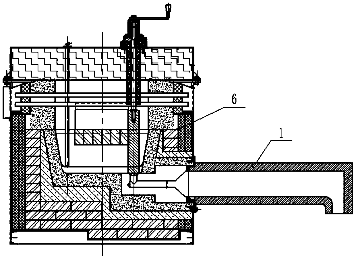
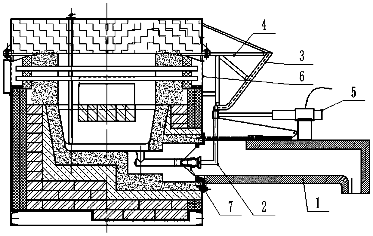
[0045] A guide tube 1 is installed on the discharge port 7 of the furnace body 6, and a skylight 8 is provided on the top surface of the inner end of the guide tube 1;

[0046] The valve stem guide frame 3 is fixedly installed on the furnace body 6 corresponding to the skylight 7 through the guide installation frame 4; the valve stem guide frame 3 includes a valve stem guide groove 9 and a connecting cross bar 10, and the valve stem guide groove 9 includes The valve stem guide groove 11 of the horizontal section and the valve stem guide groove 12 of the inclined section, the angle between the valve stem guide groove 11 of the horizontal section and the valve stem guide groove 12 of the inclined section is 125°-130°; the two valve stem guide grooves 9 The notch is relatively mirror image set through a plurality of connecting bars 10 to ...


PUM


Abstract

The invention discloses a method for blocking a pneumatic discharging valve. The method comprises the following steps that when a discharging port needs to be opened, a telescopic arm of an air cylinder is controlled to retract through an air cylinder control valve, the telescopic arm drives a sliding sleeve to move horizontally and outwards, under pulling of the sliding sleeve, a blocking valve rod slides towards the outer side of a furnace body along a horizontal section valve rod guide groove, the discharging port is opened instantly, after the discharging port is opened, the blocking valverod continues to move under horizontal pulling of the telescopic arm and the sliding sleeve, when the blocking valve rod moves to an inclined section valve rod guide groove, the blocking valve rod starts to rise, a vertical rod portion of the blocking valve rod also slides upwards and is lifted under the limiting action of the sliding sleeve, the blocking valve rod is driven to slide upwards along the inclined section valve rod guide groove, so that the blocking valve rod is moved out of a skylight port of a flow guide cylinder.

Description

technical field [0001] The invention relates to the technical field of industrial kiln equipment and valve control, in particular to a method for blocking a pneumatic discharge valve. Background technique [0002] At present, the furnace body of the metal melting furnace is welded by steel plates and section steel, and is equipped with its own burner. There is a liquid metal circulation channel between the melting room and the heat preservation room. When working, the molten metal is continuously flowing from the melting room After flowing into the heat preservation room, the molten metal flowing into the heat preservation room is heated up to the operating temperature in the heat preservation room, and the refractory mud at the discharge port is manually opened for discharge. [0003] In addition, the discharge port of the metal melting furnace is generally made of refractory cement or graphite material, and is often blocked by a metal plug with an asbestos paper cup. A lo...

Claims


Application Information

Patent Timeline
Patent Type & Authority Applications(China)
IPC IPC(8): F16K1/38F16K1/32F16K27/02F16K27/08F16K31/12F27B14/18F27D3/15
CPCF16K1/32F16K1/38F16K27/0254F16K27/08F16K31/12F27B14/0806F27B2014/0818F27D3/1536F27M2003/13
Inventor 杨佳志
Owner 杨佳志
Why Eureka
Try Eureka