Eureka AIR delivers breakthrough ideas for toughest innovation challenges, trusted by R&D personnel around the world.

Dual-layer energy gathering hood of gas cooker combustor

A gas cooker and energy-gathering hood technology, which is applied to gas fuel burners, burners, combustion methods, etc., can solve the problems of large air intake resistance, decreased oxygen content, easy to put out fire, etc., so as to reduce the concentration of CO , The effect of reducing the surface temperature and improving the thermal insulation performance

Pending Publication Date: 2019-07-12
HANGZHOU DE&E ELECTRICAL CO LTD
View PDF1 Cites 1 Cited by
  • Summary
  • Abstract
  • Description
  • Claims
  • Application Information

AI Technical Summary

Problems solved by technology

[0002] When gas cookers are in use, energy-gathering hoods are installed to reduce heat loss. At present, most energy-gathering hoods are arranged in a single-layer structure, and the heat loss of energy-gathering hoods with a single-layer structure is large. In view of this, the application number is The patent literature of 201611247951.4 discloses an energy-gathering component of a gas stove. Although the energy-gathering component in the above-mentioned reference document is double-layered, it also has the following defects: the double-layer energy-gathering cover only has combustion smoke mixed with secondary air to supply air One channel, there is not enough secondary air supply channel for the outer ring flame and the inner ring flame, the secondary air supply is less, the gas combustion is not sufficient, and the channel is inclined downward to form an angle with the horizontal direction, the air intake resistance is relatively large, At the same time, the secondary air is easily heated by the first layer of energy-concentrating cover, causing the oxygen content to drop, which is not conducive to the supplement of secondary air
The energy-gathering cover in the comparison document lacks a liquid receiving device. When the liquid in the pot overflows, it is easy to extinguish the fire and cause danger.

Method used


Image

  • Dual-layer energy gathering hood of gas cooker combustor
  • Dual-layer energy gathering hood of gas cooker combustor
  • Dual-layer energy gathering hood of gas cooker combustor

Examples


Embodiment Construction

[0035] The present invention will be further described in detail below in conjunction with the accompanying drawings and examples. The following examples are explanations of the present invention and the present invention is not limited to the following examples.

[0036] Example.

[0037] see Figure 1 to Figure 15 It should be noted that the structures, proportions, sizes, etc. shown in the drawings attached to this specification are only used to match the content disclosed in the specification, for those who are familiar with this technology to understand and read, and are not used to limit the present invention Therefore, it has no technical substantive meaning, and any modification of structure, change of proportional relationship or adjustment of size shall still fall into the within the scope covered by the technical content disclosed in the present invention. At the same time, if terms such as "upper", "lower", "left", "right", "middle" and "one" are used in this spe...


PUM


Abstract

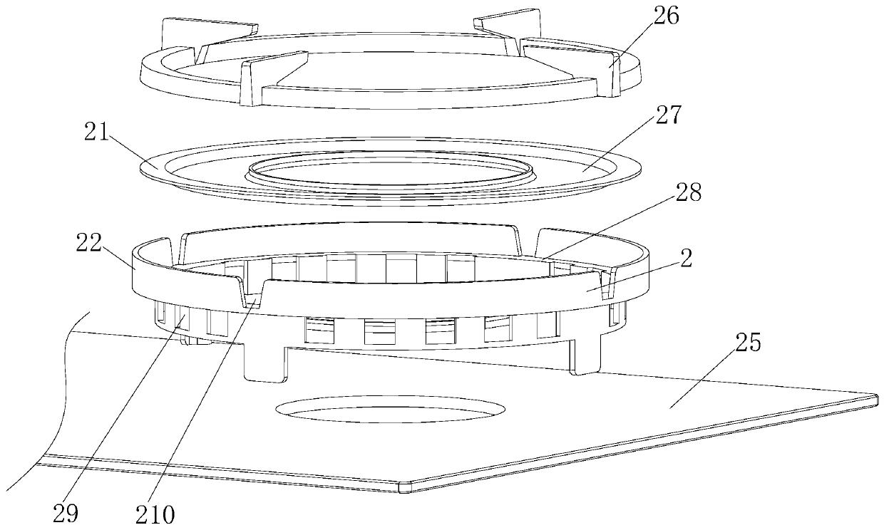
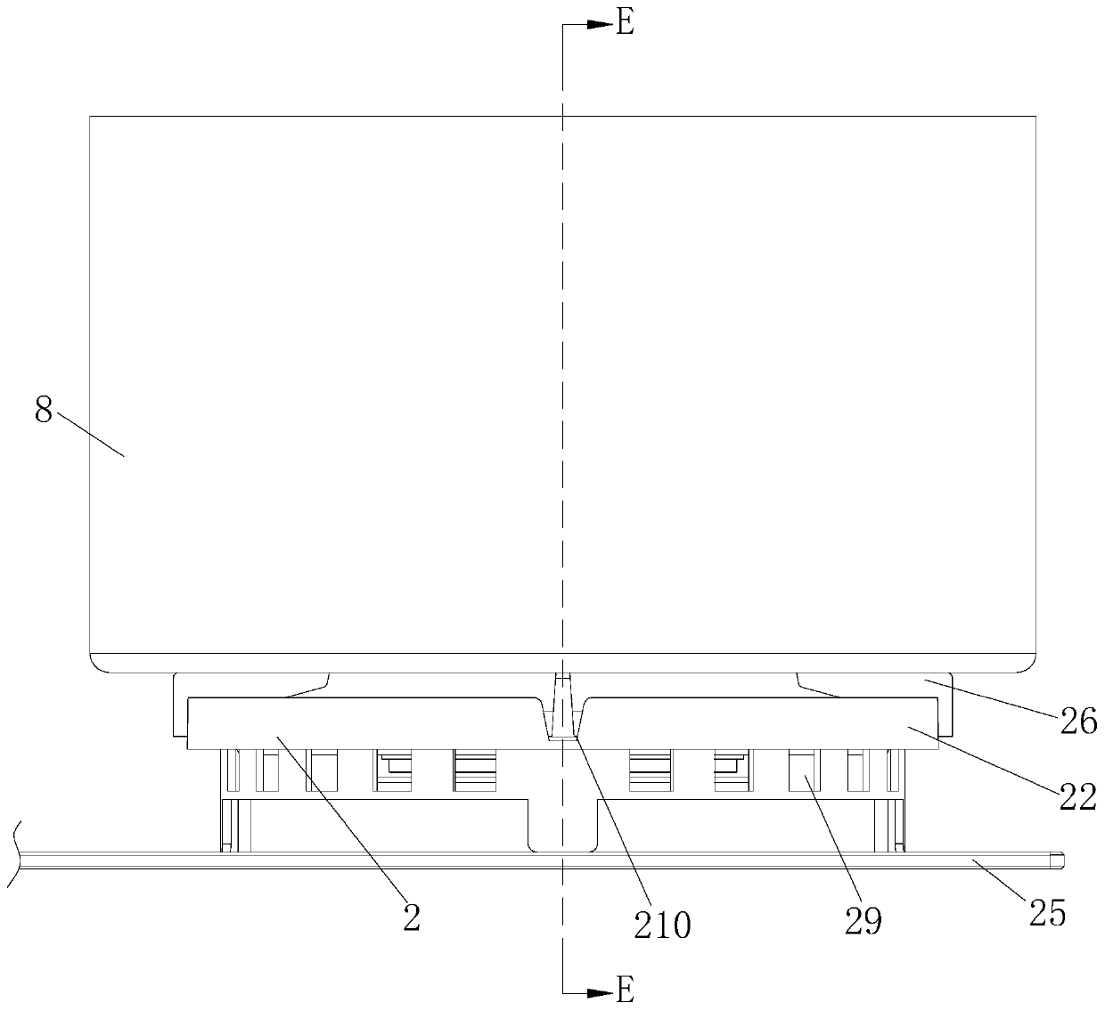
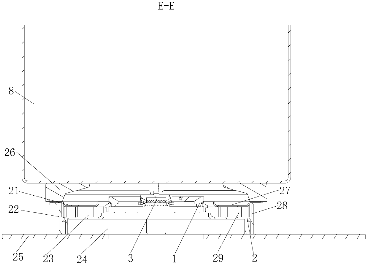
The invention relates to a dual-layer energy gathering hood of a gas cooker combustor, and belongs to the field of gas cookers. The dual-layer energy gathering hood comprises a second energy gatheringhood and is characterized by further comprising a first energy gathering hood, the first energy gathering hood is placed on the second energy gathering hood, an outer ring fire secondary air supplementing channel for supplementing secondary air to the outer ring fire is formed between the first energy gathering hood and the second energy gathering hood, an inner ring fire secondary air supplementing channel for supplementing secondary air to the inner ring fire is formed between the second energy gathering hood and a cooker panel, through the outer ring fire secondary air supplementing channel, the secondary air is supplemented to the outer ring fire, the secondary air is supplemented to the inner ring fire through the inner ring fire secondary air supplementing channel, gas is sufficiently combusted, and CO concentration standard exceeding in the smoke can be avoided.

Description

technical field [0001] The invention relates to a double-layer energy-gathering cover for a burner of a gas cooker, belonging to the field of gas cookers. Background technique [0002] When gas cookers are in use, energy-gathering hoods are installed to reduce heat loss. At present, most energy-gathering hoods are arranged in a single-layer structure, and the heat loss of energy-gathering hoods with a single-layer structure is large. In view of this, the application number is The patent document of 201611247951.4 discloses an energy-gathering component of a gas stove. Although the energy-gathering component in the above-mentioned reference document is double-layered, it also has the following defects: the double-layer energy-gathering cover only has combustion smoke mixed with secondary air to supply air One channel, there is not enough secondary air supply channel for the outer ring flame and the inner ring flame, the secondary air supply is less, the gas combustion is not ...

Claims


Application Information

Patent Timeline
Patent Type & Authority Applications(China)
IPC IPC(8): F24C15/10F24C15/14F24C3/12F23D14/46
CPCF24C15/101F24C15/107F24C15/14F24C3/126F23D14/46
Inventor 刘均高德康
Owner HANGZHOU DE&E ELECTRICAL CO LTD
Why Eureka
Eureka Blog
Learn More