
Motion artifact reduction method based on flight time depth camera

A depth camera and motion artifact technology, applied in radio wave measurement systems, instruments, etc., can solve the problems of motion artifact, limited image matching accuracy, and high algorithm complexity, and achieve the effect of reducing time difference and motion artifact

Active Publication Date: 2019-07-12
HANGZHOU LANXIN TECH CO LTD
View PDF7 Cites 7 Cited by
  • Summary
  • Abstract
  • Description
  • Claims
  • Application Information

AI Technical Summary

Problems solved by technology

However, the TOF depth camera needs to collect several related time maps to calculate a depth map. When the moving speed is fast, serious motion artifacts will appear on the edge of the object.
[0003] In order to reduce the motion artifact of the TOF depth camera, one method is to perform image matching on several relevant time maps, move the same object to the same image position, and then perform depth calculation. However, this method has a high algorithm complexity. The accuracy of image matching is also limited; another method is to use the constraint rules of several related time maps to remove the points that do not match the edge of the object, but this method cannot completely remove motion artifacts, and at the same time removes effective points

Method used


Image

  • Motion artifact reduction method based on flight time depth camera
  • Motion artifact reduction method based on flight time depth camera
  • Motion artifact reduction method based on flight time depth camera

Examples


Embodiment 1

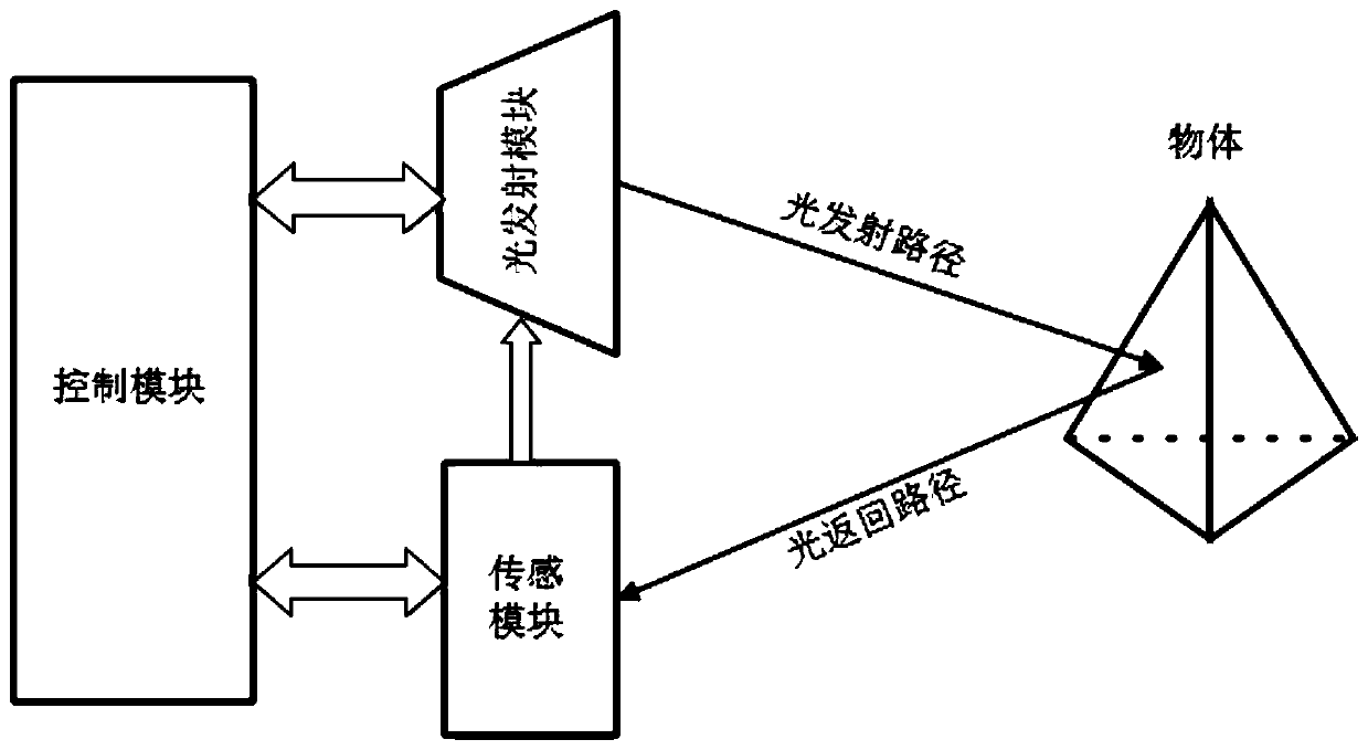
[0045] like figure 1 As shown, in the first embodiment of the present invention, the time-of-flight depth camera includes a light emitting module, a sensing module and a control module connected to each other. The light emitting module emits modulated light; the sensing module receives reflected light from objects within the receiving range; the control module controls the on / off of the light emitting module and the working status of the sensing module, and receives light signals from the sensing module, And process the light signal to get the distance between the object and the depth camera.

[0046] The motion artifact reduction method based on the above-mentioned time-of-flight depth camera of the present implementation includes the following steps:

[0047] In the first step, the light emitting module of the time-of-flight depth camera emits light outward.

[0048] As a preferred embodiment, the light emitting module is adjusted by the control module to adjust the light ...


PUM


Abstract

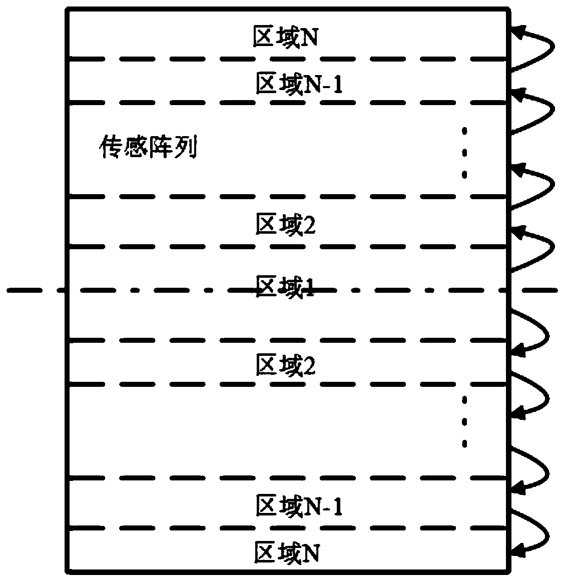
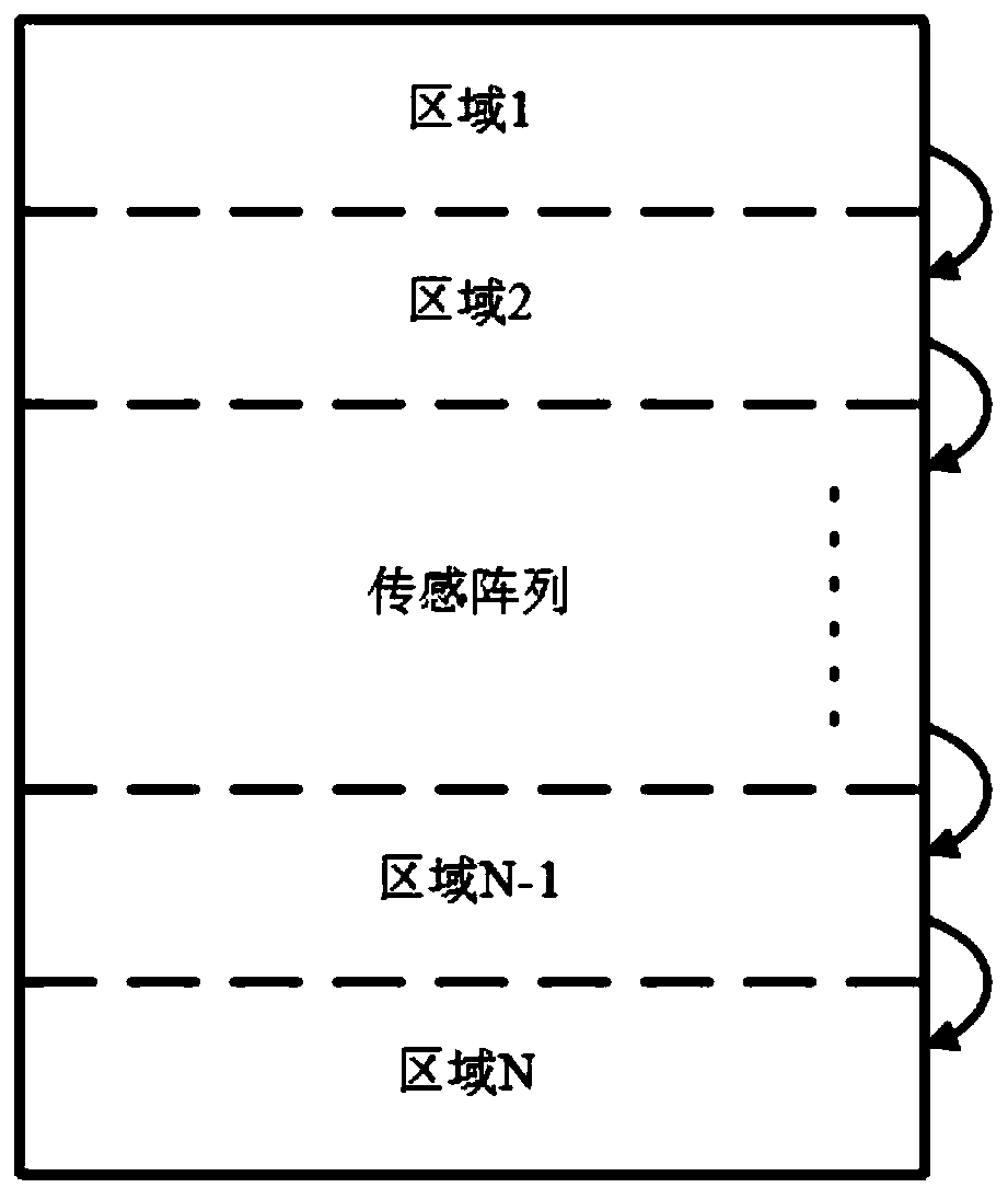
The invention discloses a motion artifact reduction method based on a flight time depth camera. The flight time depth camera comprises a light emission module, a sensing module and a control module used for controlling the light emission module and the sensing module and carrying out data storage processing. The motion artifact reduction method comprises the following steps that S1, the light emission module emits light outwards; S2, the sensing module receives a reflection light signal from a target object to generate a relevant time diagram; and S3, the control module processes the relevanttime diagram, and generates a depth map through depth calculation, wherein a sensing array of the sensing module is divided into a plurality of regions to be exposed block by block, and each region respectively and continuously acquires a plurality of relevant time diagrams for depth calculation in the step S2. According to the method, the time difference of exposure of different frames due to a data transmission process is reduced, and the phenomenon of artifact on the edge of the object under the motion condition is reduced.

Description

technical field [0001] The invention relates to the technical field of depth measurement cameras, in particular to a motion artifact reduction method based on a time-of-flight depth camera used in motion. Background technique [0002] In recent years, depth cameras have been increasingly used in fields such as face recognition, traffic statistics, driving navigation, driving obstacle avoidance, industrial part detection, and object scanning. The technologies used in depth cameras on the market can be divided into three categories: binocular, time-of-flight (TOF) and structured light. The TOF depth camera determines the distance from the object to the camera by measuring the time from when the light is emitted from the camera to when it is reflected back to the camera by the object. According to its ranging principle, TOF depth cameras can be divided into continuous wave modulation TOF (CVM_TOF) and pulsed TOF (P_TOF). CVM_TOF first sends a beam of continuous modulated ligh...

Claims


Application Information

Patent Timeline
IPC IPC(8): G01S7/481G01S7/497
CPCG01S7/4802G01S7/4814G01S7/4816G01S7/497
Inventor 刘志冬王蓉徐永奎齐伟
Owner HANGZHOU LANXIN TECH CO LTD
Learn More