
Numerical control attenuator based on capacitance compensation

A digitally controlled attenuator and capacitance compensation technology, applied to frequency-independent attenuators, electrical components, networks using active components, etc., can solve the problem of increasing attenuation flatness performance, improving loss, parasitic phase modulation, reducing design flexibility, Increase design cost and other issues, achieve flexible parasitic phase modulation, reduce size requirements, and reduce loss

Pending Publication Date: 2019-07-12
ZHEJIANG CHENGCHANG TECH
View PDF0 Cites 3 Cited by
  • Summary
  • Abstract
  • Description
  • Claims
  • Application Information

AI Technical Summary

Problems solved by technology

However, due to the existence of the parasitic capacitance of the switching transistor, the attenuator has a parasitic phase shift in different states, resulting in parasitic phase modulation, which has a greater impact especially in high frequency operation
[0003] The parasitic phase modulation of the traditional attenuator with small attenuation values ​​above can be improved by adjusting the size of the switch transistor, but this method requires the transistor switch to have an accurate model in different sizes, which increases the design cost and reduces the flexibility of the design , and this also sacrifices the performance of attenuation flatness, increases loss and has limited improvement in parasitic phase modulation

Method used


Image

  • Numerical control attenuator based on capacitance compensation
  • Numerical control attenuator based on capacitance compensation
  • Numerical control attenuator based on capacitance compensation

Examples


Embodiment Construction

[0017] Embodiments of the present invention are described in detail below, wherein the same or similar reference numerals represent the same or similar elements or elements with similar functions. The embodiments described below by referring to the figures are exemplary, and are only used to explain the present invention and not to limit the present invention.

[0018] Those skilled in the art can understand that, unless otherwise defined, all terms (including technical terms and scientific terms) used herein have the same meanings as commonly understood by those of ordinary skill in the art to which this invention belongs. It should also be understood that terms such as those defined in commonly used dictionaries should be understood to have a meaning consistent with the meaning in the context of the prior art, and unless defined as herein, will not be used in an idealized or overly formal meaning to explain.

[0019] The present invention will be further described below in ...


PUM


Abstract

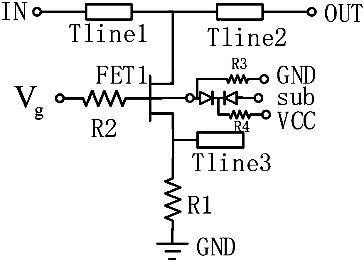
The invention discloses an attenuator based on capacitance compensation, the attenuator comprises a transistor switch, a parallel attenuation resistor, a parallel open-circuit line capacitor and a matching transmission line, and the attenuator utilizes the switch to switch an attenuation state and a direct connection state so as to realize the control of relative attenuation; the attenuator is simple in structure, small in occupied area and good in parasitic phase modulation and attenuation characteristic bandwidth, and has great advantages and application space in monolithic integrated circuit application.

Description

technical field [0001] The invention relates to the field of attenuators, more specifically, it relates to a numerically controlled attenuator based on capacitance compensation. Background technique [0002] The attenuator is an important part of the microwave control circuit, which is used to control the amplitude of the radio frequency signal. A common digitally controlled attenuator is to switch the signal between the reference state and the attenuation state through the switching device, so as to achieve the predetermined target signal amplitude attenuation. Ideally, the attenuator is equivalent to a lossless straight-through network in the reference state, and is equivalent to a resistive network with flat amplitude and phase characteristics in the attenuation state. Generally, for an attenuator with a relatively small attenuation range (less than 2dB), a simple parallel attenuation structure is used to realize a series structure of a switch and an attenuation resistor...

Claims


Application Information

Patent Timeline
IPC IPC(8): H03H11/24
CPCH03H11/245
Inventor 王立平郑骎刘利平周甲武郁发新
Owner ZHEJIANG CHENGCHANG TECH
Learn More