Flame arrester with self-cleaning function
A flame arrester and self-cleaning technology, which is applied in cleaning methods and appliances, cleaning methods using gas flow, fire rescue, etc., can solve the problems of easy blockage of flame arresters, so as to prevent the spread of flames, improve fire arresting efficiency, Effect of reducing combustible gas and oxygen concentration
- Summary
- Abstract
- Description
- Claims
- Application Information
AI Technical Summary
Problems solved by technology
Method used
Image
Examples
Embodiment 1
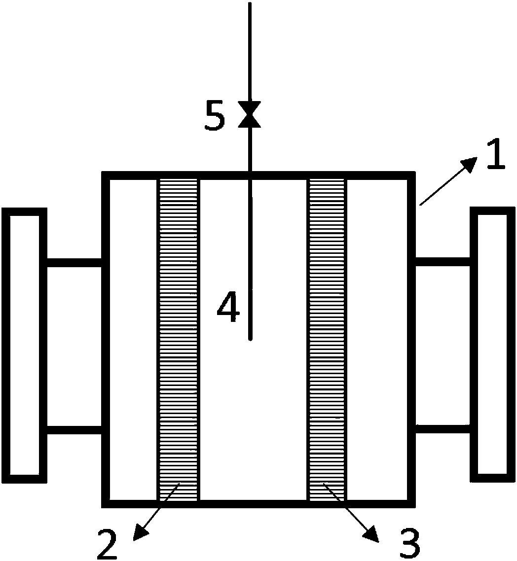
[0021] The present invention will be further described below in conjunction with the accompanying drawings and embodiments. Such as figure 1 A new flame arrester with self-cleaning function is shown, which includes a flame arrester housing 1, a left flame arresting element 2, a right flame arresting element 3, a nitrogen injection channel 4, and a nitrogen throttle valve 5.
[0022] The flame arrester casing is a metal casing that provides mechanical support and connections for the fire arresting element, and the metal is stainless steel. The fire retardant element has a porous structure, which plays a role in extinguishing the flame, and the porosity of the porous structure of the fire retardant element is 5%. The fire retardant element material is selected from stainless steel. The height of the gas injection pipeline deep into the gas injection channel is 20% of the height of the gas injection channel. According to the gas flow direction, the gas pressure before the gas ...
Embodiment 2
[0028] According to the conditions described in Embodiment 1, the shell of the flame arrester is a metal shell that provides mechanical support and connection of the fire arresting element, and the metal is carbon steel. The fire retardant element has a porous structure, which plays the role of extinguishing the flame, and the porosity of the porous structure of the fire retardant element is 80%. The material of the fire retardant element is selected from superalloy. The height of the gas injection pipeline deep into the gas injection channel is 80% of the height of the gas injection channel. According to the gas flow direction, the gas pressure before the gas throttle valve is 0.6MPa, the temperature is 15°C, the gas pressure after the gas throttle valve is 20kPa, and the temperature is 10°C. The ratio of the total volume of the fire retardant element to the volume of the gas injection channel is 1:5.
[0029] After the external nitrogen is decompressed and cooled through t...
Embodiment 3
[0034] According to the conditions described in Embodiment 1, the shell of the flame arrester is a metal shell that provides mechanical support and connection of the fire arresting element, and the metal is stainless steel. The fire retardant element has a porous structure, which plays the role of extinguishing the flame, and the porosity of the porous structure of the fire retardant element is 50%. The material of the fire retardant element is selected from aluminum. The height of the gas injection pipeline deep into the gas injection channel is 50% of the height of the gas injection channel. According to the gas flow direction, the gas pressure before the gas throttle valve is 0.4MPa, the temperature is 25°C, the gas pressure after the gas throttle valve is 10kPa, and the temperature is 20°C. The ratio of the total volume of the fire retardant element to the volume of the gas injection channel is 1:1.
[0035] After the external nitrogen is decompressed and cooled through ...
PUM
 Abstract
Description
Claims
Application Information
 - R&D
- Intellectual Property
- Life Sciences
- Materials
- Tech Scout
- Unparalleled Data Quality
- Higher Quality Content
- 60% Fewer Hallucinations
Browse by: Latest US Patents, China's latest patents, Technical Efficacy Thesaurus, Application Domain, Technology Topic, Popular Technical Reports.
© 2025 PatSnap. All rights reserved.Legal|Privacy policy|Modern Slavery Act Transparency Statement|Sitemap|About US| Contact US: help@patsnap.com

