Micro heat pipe electric-current-assisted rotary draw bending forming device and method

A micro heat pipe and bending technology, which is applied to forming tools, heat exchange equipment, manufacturing tools, etc., can solve problems such as the decrease of heat transfer capacity, and achieve the effects of improving production efficiency, suppressing cross-section distortion and low efficiency.

Active Publication Date: 2019-07-16
HARBIN INST OF TECH
View PDF5 Cites 2 Cited by
  • Summary
  • Abstract
  • Description
  • Claims
  • Application Information

AI Technical Summary

Problems solved by technology

[0004] In order to overcome the deficiencies in the prior art, the present invention proposes a micro-heat pipe current-assisted bending forming device and method. The application of the present invention can control the bending and forming defects and forming accuracy of the micro-heat pipe, and can overcome the problems such as the significant decline in heat transfer capacity of the micro-heat pipe after bending.

Method used


Image

  • Micro heat pipe electric-current-assisted rotary draw bending forming device and method
  • Micro heat pipe electric-current-assisted rotary draw bending forming device and method
  • Micro heat pipe electric-current-assisted rotary draw bending forming device and method

Examples


specific Embodiment approach 1

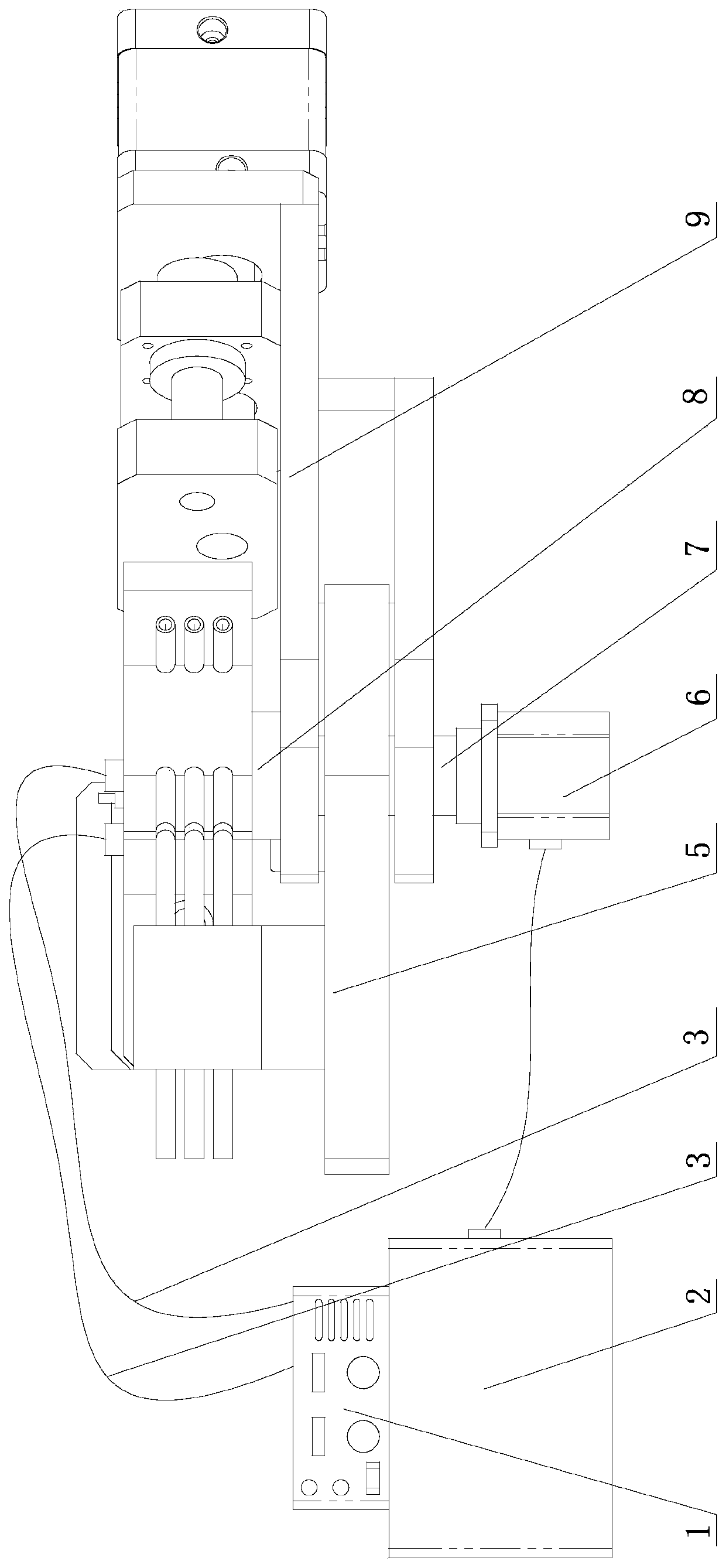
[0025] Specific implementation mode one: combine Figure 1 to Figure 2 Describe this embodiment, a micro heat pipe current-assisted bending forming device of this embodiment, including a bending forming machine, a mold assembly and an auxiliary forming power supply system, the mold assembly is installed on the bending forming machine, and the auxiliary forming power supply system is connected to the mold assembly or directly It is connected with the micro heat pipe blank 17 to provide high-density current to the micro heat pipe blank 17 during the forming process.

[0026] The winding forming machine described in this embodiment is mainly composed of a fixed base plate 5, a pressure pipe assembly, a pipe bending assembly, a rotating shaft 7, a rotating drive mechanism 6, and a control system 2; There is a rotating shaft 7, and the rotating shaft 7 cooperates with the shaft hole on the fixed base plate 5 to connect the elbow assembly and the fixed base plate 5 together, the pre...

specific Embodiment approach 2

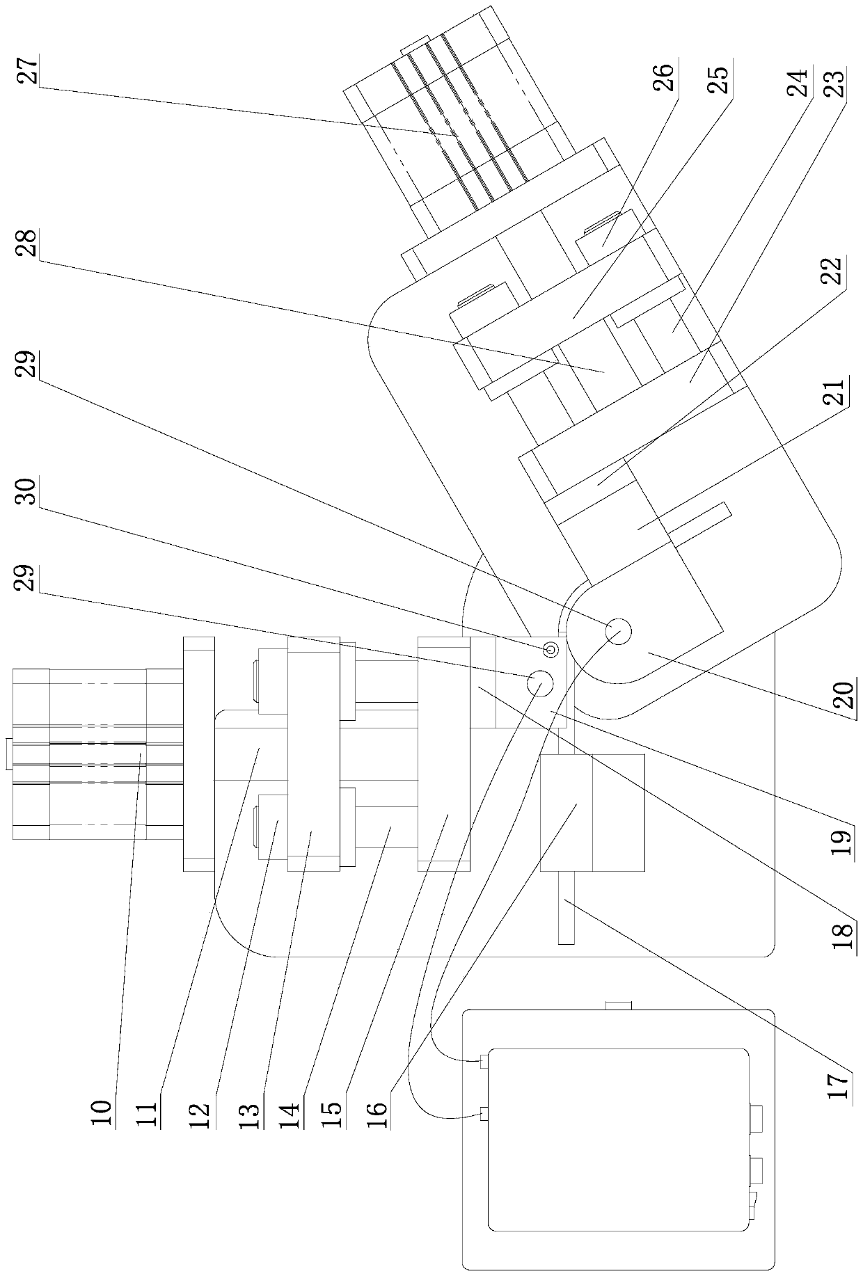
[0029] Specific implementation mode two: combination Figure 1 to Figure 2 Describe this embodiment mode, the pressure tube assembly of a current-assisted bending forming device for micro heat pipes in this embodiment includes a pressure tube thrust mechanism 10, a pressure tube push rod 11, a pressure tube push plate 15, a pressure tube guide sleeve 12, a pressure tube guide Column 14 and pressure tube guide plate 13; pressure tube thrust mechanism 10 and pressure tube guide plate 13 are fixed on the fixed base plate 5, one end of pressure tube push rod 11 is connected with pressure tube thrust mechanism 10, and the other end passes through the pressure tube guide plate The via hole on the 13 is connected with the pressure tube push plate 15, and the pressure tube guide plate 13 is connected with the pressure tube push plate 15 by the pressure tube guide post 14 and the pressure tube guide sleeve 12. The pressure tube guide plate 13 guides the reciprocating translational moveme...

specific Embodiment approach 3

[0031] Specific implementation mode three: combination Figure 1 to Figure 2 Describe this embodiment, the elbow assembly of a current-assisted bending forming device for micro heat pipes in this embodiment includes an elbow thrust mechanism 27, an elbow push rod 28, an elbow push plate 23, a rotating base 9, and an elbow guide sleeve 26 , curved pipe guide post 24 and curved pipe guide plate 25; shaft hole is processed on the rotating base 9, and the rotating shaft 7 cooperates with the shaft hole and is fixed on the rotating base 9, and the curved pipe thrust mechanism 27 and the curved pipe guiding plate 25 are all Fixed on the rotating base 9, one end of the elbow push rod 28 is connected with the elbow thrust mechanism 27, and the other end passes through the hole on the elbow guide plate 25 to connect with the elbow push plate 23, and the elbow guide plate 25 passes through the elbow The guide post 24 and the elbow guide sleeve 26 are connected with the elbow push plate ...


PUM

PropertyMeasurementUnit
thicknessaaaaaaaaaa

Abstract

The invention provides a micro heat pipe electric-current-assisted rotary draw bending forming device and method, and belongs to the technical field of bent pipe manufacture plastic micro forming. Themicro heat pipe electric-current-assisted rotary draw bending forming device comprises a rotary draw bending forming machine, a mold assembly and a forming assisting power system. The mold assembly is installed on the rotary draw bending forming machine. The rotary draw bending forming machine is mainly composed of a fixed bottom plate, a pipe pressing assembly, a pipe bending assembly, a rotating shaft, a rotation drive mechanism and a control system. The rotating shaft is installed on the pipe bending assembly and is matched with a shaft hole in the fixed bottom plate. The pipe pressing assembly is fixed to the fixed bottom plate. The forming method includes the steps that firstly, the mold assembly is selected; secondly, a power-on loop is established; thirdly, parameters are set; fourthly, micro heat pipe blank heating and bending forming are conducted; fifthly, a bent piece is obtained through bending forming; and sixthly, the bent piece is taken out. By means of the micro heat pipe electric-current-assisted rotary draw bending forming device and method, micro heat pipe bending forming defects and forming precision can be controlled, and the problem that the heat conduction capacity is lowered after micro heat pipe bending is solved.

Description

technical field [0001] The invention belongs to the technical field of plastic micro-forming in the manufacture of bent pipes, and in particular relates to a micro-heat pipe current-assisted bending forming device and method. Background technique [0002] With the continuous development of science and technology such as space technology, earth technology and ocean technology, there is an urgent need for miniaturization technology, and more and more electronic components with high heat flux density are integrated in an extremely small space, making thermal control technology a The key to the development of miniaturization. As a high-efficiency heat transfer element that uses the phase change of the working fluid in the closed tube to conduct heat transfer, the micro heat pipe is considered to be an ideal means to solve the problem of micro-mechanical thermal control, and can provide an efficient and reliable solution for the cooling of electronic components in a small space. ...

Claims


Application Information

Patent Timeline
Patent Type & Authority Applications(China)
IPC IPC(8): B21D7/024B21D7/16B21D37/10B21C51/00B21D53/06
CPCB21C51/00B21D7/024B21D7/162B21D37/10B21D53/06
Inventor 郭斌汪鑫伟徐杰单德彬
Owner HARBIN INST OF TECH
Why Eureka
Try Eureka