
Intelligent metal laser welding equipment

A laser welding machine and laser welding technology, applied in laser welding equipment, welding equipment, metal processing equipment, etc., can solve the problems of small welding operation direction, low precision, lack of laser scanner, etc., and achieve convenient movement, safe and convenient use , Structural scientific and reasonable effect

Inactive Publication Date: 2019-07-16
姜玉娟
View PDF0 Cites 1 Cited by
  • Summary
  • Abstract
  • Description
  • Claims
  • Application Information

AI Technical Summary

Problems solved by technology

[0003] The present invention provides an intelligent metal laser welding equipment, which can effectively solve the problem that the traditional manually operated laser welding machine proposed in the above-mentioned background technology has a large risk factor and does not have a horizontal rotation device, which leads to a relatively difficult welding operation direction when it is used. It is small and does not have the adjustment function in the vertical direction, so that the existing welding machine cannot be applied to the welding process of various materials. The lack of sensing elements such as laser scanners and distance measuring sensors results in relatively low welding position accuracy of the existing laser welding machine. low level problem

Method used


Image

  • Intelligent metal laser welding equipment
  • Intelligent metal laser welding equipment
  • Intelligent metal laser welding equipment

Examples


Embodiment Construction

[0017] The preferred embodiments of the present invention will be described below in conjunction with the accompanying drawings. It should be understood that the preferred embodiments described here are only used to illustrate and explain the present invention, and are not intended to limit the present invention.

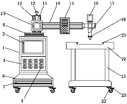
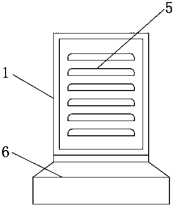
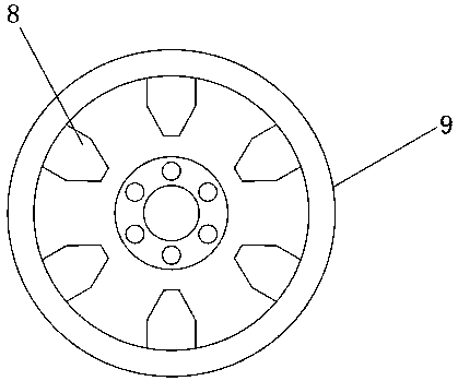
[0018] Example: such as Figure 1-4 As shown, the present invention provides a technical solution, an intelligent metal laser welding equipment machine, including a laser welding machine 1, a main control display panel 2, a matrix operation button 3, a control switch 4, a ventilation louver hole 5, and a fixed base 6 , high thermal conductivity strip 7, horizontal rotary plate 8, engaging convex teeth 9, fixed plate 10, movable chute 11, tightening knob 12, fixed panel 13, movable beam 14, pulse generator 15, laser scanner 16, Telescopic forearm 17, distance measuring sensor 18, laser welding table 19, engaging bump 20, support column 21, moving wheel 22 and brake 2...


PUM


Abstract

The invention discloses intelligent metal laser welding equipment which comprises a main control display board, breathing louver holes, a horizontal rotating disc, movable sliding grooves, a telescopic front arm and moving wheels. The breathing louver holes are formed in the outer side of the main control display board, the movable sliding grooves are formed above the horizontal rotating disc, andthe moving wheels are arranged under the telescopic front arm. The intelligent metal laser welding equipment is scientific and reasonable in structure, and safe and convenient to use, and the main control display board can systematically and intelligently control welding information data of a laser welding machine; the breathing louver holes can be used for timely dissipating heat generated by the laser welding machine; the horizontal rotating disc can be used for conveniently adjusting the horizontal welding direction of the laser welding machine; the movable sliding grooves and the telescopic front arm are used for conveniently adjusting the welding height in the vertical direction of the laser welding machine; the moving wheels are arranged to enable the laser welding machine to be more conveniently moved before and after use.

Description

technical field [0001] The invention relates to the technical field of laser welding equipment, in particular to an intelligent metal laser welding equipment. Background technique [0002] With the continuous development of modern industry, the appetite range of the laser welding machine is gradually increasing. The laser welding machine mainly uses high-energy laser pulses to locally heat the welding materials in a small range, and the energy of the laser radiation makes the heat Diffusion to the inside of the material until the material is melted to form a characteristic molten pool to achieve the welding effect. The existing laser welding machine is generally operated manually, because of its high risk factor during operation, it is easy to cause harm to people. At the same time, manual welding can easily cause a deviation between the welding machine port and the welding spot of the welding material, which affects the welding effect on the material. The existing laser wel...

Claims


Application Information

Patent Timeline
IPC IPC(8): B23K26/21B23K26/70B23K26/08
CPCB23K26/0884B23K26/21B23K26/702B23K26/703
Inventor 姜玉娟
Owner 姜玉娟
Learn More