Decorative moulding sawing machine

A technology of decorative lines and sawing machines, applied in sawing components, sawing equipment, circular saws, etc., can solve problems such as increased production costs, waste of production raw materials, waste decorative lines, etc., to improve work efficiency and reduce labor intensity , The effect of high sawing precision

Pending Publication Date: 2019-07-16
NANTONG YUETONG CNC EQUIP CO LTD
View PDF5 Cites 4 Cited by
  • Summary
  • Abstract
  • Description
  • Claims
  • Application Information

AI Technical Summary

Problems solved by technology

[0005] The sawing method in the prior art is manually operated, the workload of the operator is large, time-consuming and laborious, and because the angle of cutting is related to the proficiency of the operator, there is generally a certain error in the angle of sawing. If the error is large, it is easy to cause the decorative lines to be unable to be installed, so that the decorative lines become waste products, resulting in waste of raw materials and increased production costs

Method used


Image

  • Decorative moulding sawing machine
  • Decorative moulding sawing machine
  • Decorative moulding sawing machine

Examples


Embodiment Construction

[0062] The terms "first", "second", etc. used herein do not specifically refer to a sequence or order, nor are they used to limit the present application, but are only used to distinguish components or operations described with the same technical terms. .

[0063] In order to make the object, technical solution and advantages of the present invention clearer, the implementation manner of the present invention will be further described in detail below in conjunction with the accompanying drawings.

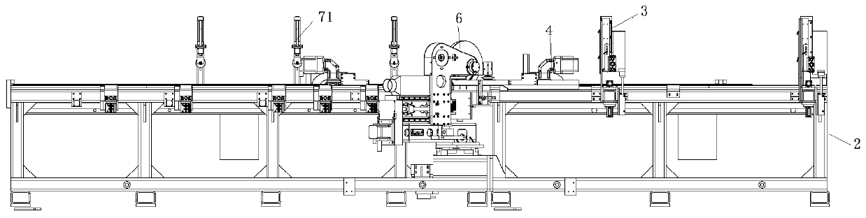
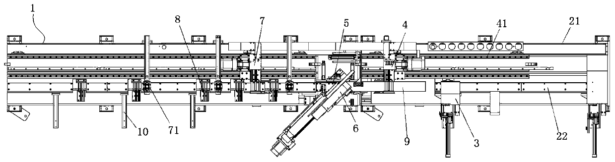
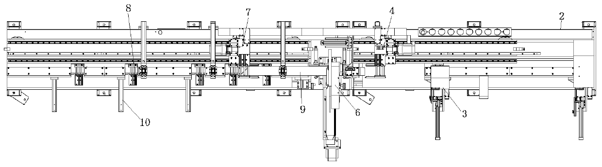
[0064] In an embodiment of the present invention, please refer to figure 1, which shows a front structural schematic diagram of a decorative line sawing machine 1 according to an embodiment of the present invention. The decorative line sawing machine 1 can saw any workpiece suitable for sawing in the present invention, including but not limited to structures such as decorative lines 9 and planks. The cutting machine 1 comprises a frame 2, a front clamping device 4, a sawing table ...


PUM


Abstract

The invention relates to a decorative moulding sawing machine. The decorative moulding sawing machine comprises a rack, a sawing workbench assembly, a rotatable sawing assembly and a rear clamping device. The rack is provided with a table board. The sawing workbench assembly and a front clamping device are connected to be arranged on the rack, and the sawing workbench assembly is used for clampingand locating decorative mouldings. The rotatable sawing assembly is arranged on the rack in a manner of corresponding to the sawing workbench assembly and is used for sawing the decorative mouldings.The rear clamping device is connected with the sawing workbench assembly to be arranged on the rack and is used for locating and conveying the decorative mouldings. When the front clamping device conveys the decorative mouldings onto the sawing workbench assembly, the decorative mouldings are clamped and located by the sawing workbench assembly, and one ends of the decorative mouldings are sawn by the rotatable sawing assembly. When the rear clamping device locates the decorative mouldings, the decorative mouldings are clamped and located by the sawing workbench assembly. According to the decorative moulding sawing machine, manual operation is replaced, the labor intensity of workers is reduced, and the work efficiency is improved through cooperation of the front clamping device and the rear clamping device.

Description

technical field [0001] The invention relates to a sawing machine, in particular to a decorative line sawing machine. Background technique [0002] At present, before the splicing of the decorative lines, it is necessary to cut the corners of the ends of the decorative lines first, and then splicing, especially in the process of making wooden doors in some furniture companies, it is necessary to cut the ends of a large number of wooden door decorative lines. horn. [0003] The angle cutting method in the prior art is usually that workers use a single sawing surface to cut, then manually move the decorative line, and then saw the other side, so that at least two cuts are usually required to form the required angle. [0004] In the process of realizing the present invention, the inventor finds that there are at least the following problems in the prior art: [0005] The sawing method in the prior art is manually operated, the workload of the operator is large, time-consuming ...

Claims


Application Information

Patent Timeline
Patent Type & Authority Applications(China)
IPC IPC(8): B27G3/00B27B5/04B27B5/29B27B31/00B27B29/02
CPCB27G3/00B27B5/04B27B5/29B27B31/00B27B29/02
Inventor 陆春伟邵小路丁仁杰范进
Owner NANTONG YUETONG CNC EQUIP CO LTD
Why Eureka
Try Eureka