
Water supply and drainage mechanism at pool bottom of assembly type swimming pool.

A prefabricated, water supply and drainage technology, which is applied in swimming pools, public buildings, gymnasiums, etc., can solve problems such as turbulent water flow in pools, inability to drain water in drainage pools, poor puncture resistance and frost resistance of adhesive films, and achieve easy The effect of widening and easy assembly

Pending Publication Date: 2019-07-16
江阴四方游泳康复产业股份有限公司
View PDF1 Cites 4 Cited by
  • Summary
  • Abstract
  • Description
  • Claims
  • Application Information

AI Technical Summary

Problems solved by technology

The film has excellent waterproof performance and deformation resistance, but the puncture resistance and frost resistance of the film are poor
[0003] And its water intake mode of present swimming pool is usually to offer water inlet at the bottom of the pool, and the water inlet is connected with the external water inlet pipeline, and carries out water supply and pumping by the water pump, because the water inlet is usually positioned at a corner of the bottom of the pool, at the inlet It is easy to cause turbulence in the water flow in the pool, and the water at the bottom of the pool cannot be drained in the drainage pool. Therefore, it is necessary to improve the existing swimming pool drainage / water intake system

Method used


Image

  • Water supply and drainage mechanism at pool bottom of assembly type swimming pool.
  • Water supply and drainage mechanism at pool bottom of assembly type swimming pool.
  • Water supply and drainage mechanism at pool bottom of assembly type swimming pool.

Examples


Embodiment 1

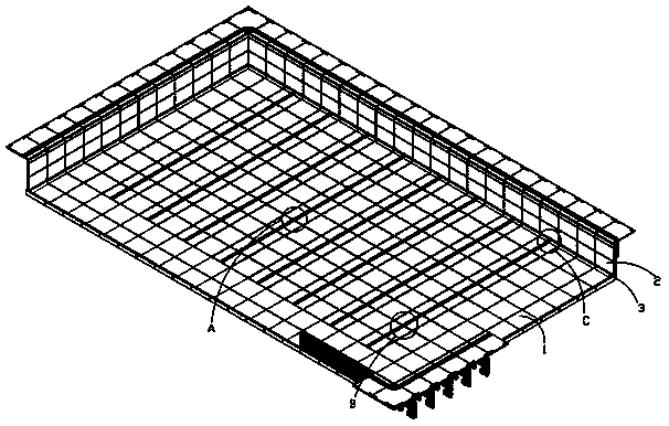
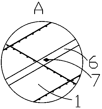
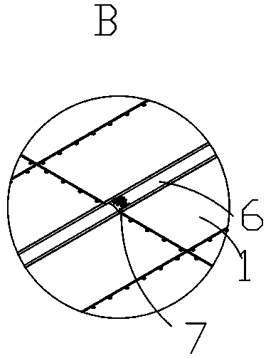
[0020] Embodiment one: if figure 1 , figure 2 , Figure 4 As shown, a prefabricated swimming pool bottom water supply and drainage mechanism includes a swimming pool bottom formed by splicing several pool bottom plates 1, an inner wall 2 vertically arranged around the bottom of the swimming pool, and connected to the swimming pool. The pool edge plate 3 between the edge of the pool bottom and the lower edge of the inner wall plate 2, the connection between the inner wall plate 2 and the adjacent inner wall plate 2 or the pool edge plate 3, the A sealing structure is provided between the pool bottom plate 1 and the adjacent pool bottom plate 1 or the pool side plate 3, the sealing structure can be installed with sealant or a sealing strip is set between the two, the same row or In the same row, the pool bottom plate 1 and the pool side plate 3 are provided with a water supply / drainage groove 4, and the outer side of the inner wall plate 2 is provided with a water supply pipe...

Embodiment 2

[0025] Embodiment two, such as image 3 As shown, the difference from Embodiment 1 is that the cover plate 6 is an arc-shaped plate, and the structure of the arc-shaped plate makes the swimming pool drain more thoroughly without causing residual phenomenon, which greatly facilitates the water exchange work of the swimming pool.


PUM


Abstract

The invention discloses a water supply and drainage mechanism at the pool bottom of an assembly type swimming pool. The water supply and drainage mechanism comprises a swimming pool bottom formed by splicing a plurality of pool bottom plates, an inner coaming vertically surround the periphery of the swimming pool bottom, and pool edge plates connected between the edge part of the swimming pool bottom and the lower edge part of the inner coaming. The pool bottom plates and the pool edge plates in the same row or column are provided with water supply / drainage grooves, a water supply pipeline isarranged on the outer side of the inner coaming, a circulating water pump is arranged on the water supply pipeline, the pool edge plate on one side is provided with a through hole for communicating the water supply pipeline with the water supply / drainage groove, the water supply / drainage groove is covered with a cover plate, and the cover plate is provided with a perforation through which water flows, so that the disassembly and assembly are convenient, and a water supply / drainage pipeline is easy to be processed on the pool bottom plates, so that the water supply / drainage of the swimming poolis convenient.

Description

technical field [0001] The invention relates to a water supply and drainage mechanism for the bottom of an assembled swimming pool. Background technique [0002] CN105804441A discloses a new type of disassembled swimming pool, which uses a square frame, angle steel connecting rods, and load-bearing steel beams to form a rigid main structure of the swimming pool. water. The adhesive film has excellent waterproof performance and deformation resistance, but the puncture resistance and frost resistance of the adhesive film are poor. [0003] And its water intake mode of present swimming pool is usually to offer water inlet at the bottom of the pool, and the water inlet is connected with the external water inlet pipeline, and carries out water supply and pumping by the water pump, because the water inlet is usually positioned at a corner of the bottom of the pool, at the inlet It is easy to cause turbulence in the water flow in the pool, and the water at the bottom of the pool ...

Claims


Application Information

Patent Timeline
Patent Type & Authority Applications(China)
IPC IPC(8): E04H4/12
CPCE04H4/1236
Inventor 史瑞丰万海东
Owner 江阴四方游泳康复产业股份有限公司
Learn More