
Substrate integrated gradient-width surface wave antenna

A substrate integration and surface wave technology, applied in the field of communication antennas, can solve the problems of narrow gain bandwidth, difficult processing, large dispersion coefficient, etc., and achieve the effect of easy processing, high gain, and low profile

Active Publication Date: 2019-07-16
SUN YAT SEN UNIV
View PDF2 Cites 2 Cited by
  • Summary
  • Abstract
  • Description
  • Claims
  • Application Information

AI Technical Summary

Problems solved by technology

[0007] The above solution (1) needs to gradually reduce the thickness of the dielectric waveguide, and this structure is not easy to process; the above solution (2) has a relatively narrow gain bandwidth in the end-fire direction due to the relatively large dispersion coefficient; the above solution (3) Requires air as a medium and is not easy to process

Method used


Image

  • Substrate integrated gradient-width surface wave antenna
  • Substrate integrated gradient-width surface wave antenna
  • Substrate integrated gradient-width surface wave antenna

Examples


Embodiment Construction

[0029] The following will clearly and completely describe the technical solutions in the embodiments of the present invention with reference to the accompanying drawings in the embodiments of the present invention. Obviously, the described embodiments are only part of the embodiments of the present invention, not all of them. Based on the embodiments of the present invention, all other embodiments obtained by persons of ordinary skill in the art without creative efforts fall within the protection scope of the present invention.

[0030] It should be noted that if there is a directional indication (such as up, down, left, right, front, back...) in the embodiment of the present invention, the directional indication is only used to explain the position in a certain posture (as shown in the accompanying drawing). If the specific posture changes, the directional indication will also change accordingly.

[0031] In addition, if there are descriptions involving "first", "second" and ...


PUM


Abstract

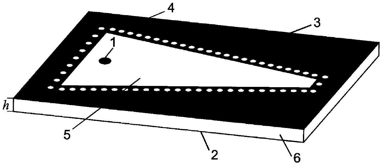
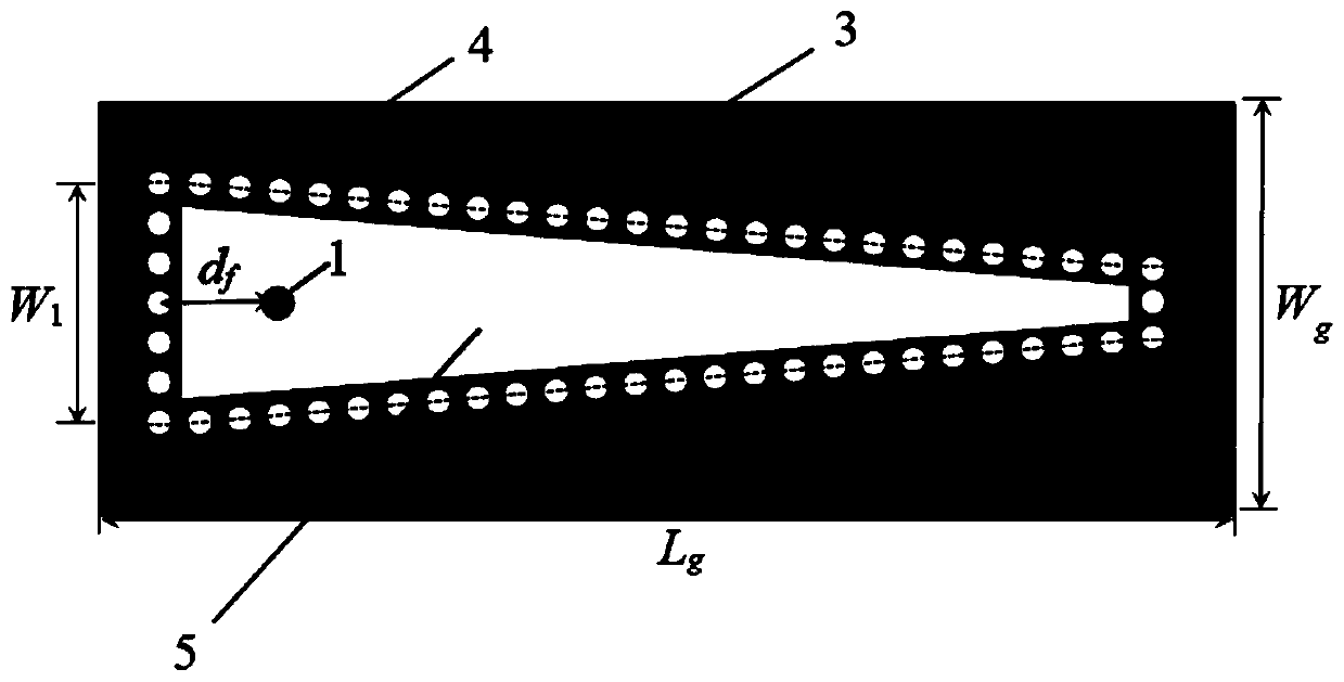
The invention discloses a substrate integrated gradient-width surface wave antenna. The antenna comprises a metal floor, an upper-layer metal plate, a dielectric plate, a short circuit via hole and afeed probe, wherein the upper-layer metal plate and the metal floor are positioned on the upper surface and the lower surface of the dielectric plate respectively; the upper-layer metal plate is provided with an empty groove along the transverse gradient width; the short circuit via hole is arranged along the edge of the empty groove; and the feed probe is arranged in the longitudinal center of the empty groove and penetrates through the dielectric plate to be connected with the upper-layer metal plate. The antenna realizes high-gain and low-sidelobe-level end-on-fire radiation, provides a relatively wide impedance bandwidth, and has the characteristics of easy integration, low profile and easy processing.

Description

technical field [0001] The invention relates to the field of communication antennas, in particular to a substrate-integrated tapered-width surface wave antenna. Background technique [0002] The surface wave antenna is a commonly used end-fire antenna. The traditional dielectric-based surface wave antenna mainly has two structures: a dielectric rod and a dielectric plate. The structural parameters of the dielectric rod along the propagation direction or the thickness of the dielectric plate are gradually reduced. It can make the surface wave antenna obtain better radiation performance. However, this gradient structure is not easy to process. [0003] Commonly used high-gain end-fire antenna implementations are: [0004] (1) dielectric waveguide slot antenna; [0005] (2) A leaky-wave antenna with longitudinal narrow slots dug on the wide surface of the rectangular waveguide; [0006] (3) Leaky wave antenna with quasi-TEM guided wave structure. [0007] The above solutio...

Claims


Application Information

Patent Timeline
IPC IPC(8): H01Q1/36H01Q1/38H01Q1/50
CPCH01Q1/36H01Q1/38H01Q1/50
Inventor 刘菊华张舒婕
Owner SUN YAT SEN UNIV
Learn More