Hot-forging die lower die with internal cooling function and cooling method thereof

A technology of hot forging dies and functions, which is applied in heating/cooling equipment, manufacturing tools, forging/pressing/hammer devices, etc., and can solve problems such as reducing die life, environmental pollution in workshops, bonding and ejection force of dies and forgings, etc. , to achieve sufficient cooling and avoid the effect of dragging the hose

Active Publication Date: 2019-07-19
安徽康尼精密机械有限公司
View PDF6 Cites 2 Cited by
  • Summary
  • Abstract
  • Description
  • Claims
  • Application Information

AI Technical Summary

Problems solved by technology

The disadvantage of this lubrication method is that there will be a large amount of graphite vapor, which will cause environmental pollution in the workshop
In the hot forging form with a large amount of water, the mold does not need to be heated, but it needs to be cooled in time to keep the mold at room temperature during the production process, and the residual water on the surface of the mold during rapid forming is instantly vaporized into water vapor for lubrication. In time, the die and forging will have a phenomenon of bonding and a sharp increase in ejection force, which greatly reduces the life of the die, and sometimes even causes the product to fail to form. Therefore, it is necessary to cool in the lower die and upper die in time.

Method used


Image

  • Hot-forging die lower die with internal cooling function and cooling method thereof
  • Hot-forging die lower die with internal cooling function and cooling method thereof
  • Hot-forging die lower die with internal cooling function and cooling method thereof

Examples


Embodiment Construction

[0038] The present invention will be further explained below in conjunction with the accompanying drawings and specific embodiments. It should be understood that the following specific embodiments are only used to illustrate the present invention but not to limit the scope of the present invention.

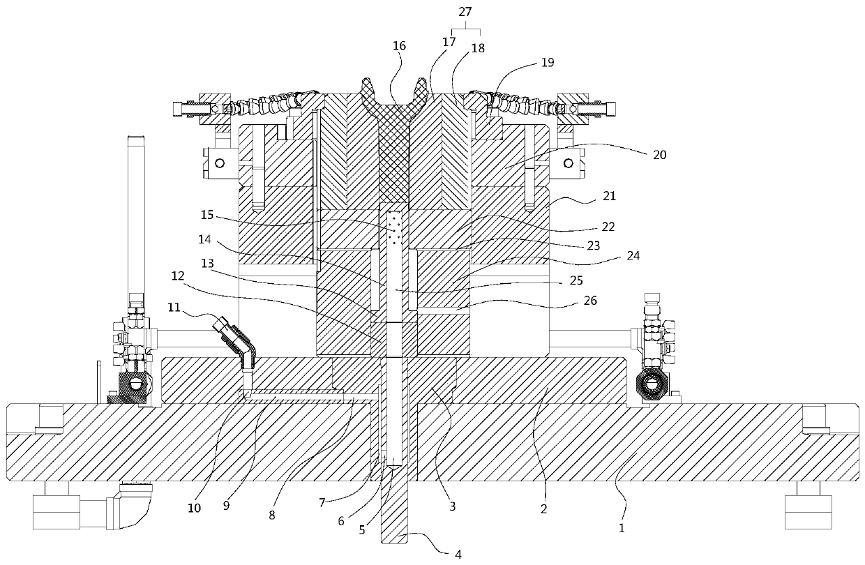
[0039] figure 1 It is a schematic structural view of the present invention, and it can be seen in conjunction with the accompanying drawings that the lower mold of the present invention includes a lower mold frame, a support pad mechanism, a die 27, a die fixing mechanism and a cooling system.

[0040] The lower formwork includes a lower backing plate 1 and a lower formwork 2, the lower backing plate 2 is fixed on the lower backing plate 1, the lower backing plate 1 and the lower formwork 2 are provided with coaxial through holes, and a lower T is arranged in the through holes. Type spacer 3, lower T-type spacer 3 is provided with push rod through hole vertically.

[0041] The s...


PUM


Abstract

The invention discloses a hot-forging die lower die with an internal cooling function and a cooling method thereof. The hot-forging die lower die comprises a lower die frame, a concave die supportingcushion block mechanism, a concave die, a concave die fixing mechanism and a cooing system. The cooling method comprises the steps that water enters the cooling system, is sprayed out from water spraying holes of a lower ejection rod in a die closing state, and flows out from a side hole of a lower first cushion block; after an upper die is lifted up, the water flows out from an air hole formed between the lower first cushion block and a lower second cushion block; after the die is opened, a forge piece is carried away by a manipulator, and the water directly flows into a middle die cavity ofthe concave die; a blank is installed in the concave die through the manipulator, the redundant water in the concave die is drained out through the blank, and the water in the through hole of the lower first cushion block is drained through the side hole of the lower first cushion block; and the blank is moved downwards, the side hole of the lower first cushion block is blocked by an adjusting block, and the water in the through hole of the lower first cushion block is drained out through an air hole formed between the lower first cushion block and a lower T-shaped cushion block. According tothe hot-forging die lower die with the internal cooling function and the cooling method thereof, the concave die is cooled fully, timely, efficiently and comprehensively.

Description

technical field [0001] The invention relates to a lower die of a hot forging die with an internal cooling function and a cooling method thereof, belonging to the technical field of hot forging cooling. Background technique [0002] In traditional hot forging, the mold needs to be heated to about 200°C, and the mold is lubricated by spraying graphite suspension on the surface of the mold. After evaporation, the residual graphite acts as a lubricating medium at high temperature. The disadvantage of this lubrication method is that there will be a large amount of graphite vapor, which will cause environmental pollution in the workshop. In the hot forging form with a large amount of water, the mold does not need to be heated, but it needs to be cooled in time to keep the mold at room temperature during the production process, and the residual water on the surface of the mold during rapid forming is instantly vaporized into water vapor for lubrication. In time, the die and forgin...

Claims


Application Information

Patent Timeline
Patent Type & Authority Applications(China)
IPC IPC(8): B21J13/02B21K29/00
CPCB21J13/02B21K29/00
Inventor 袁天宇
Owner 安徽康尼精密机械有限公司
Why Eureka
Try Eureka