Stepped gravity heat pipe geothermal exploitation system without liquid accumulation effect

A gravity heat pipe, step-type technology, applied in the field of step-type gravity heat pipe geothermal mining system, can solve the problems of heat transfer efficiency reduction of heat pipe, liquid working medium cannot evaporate, etc., to avoid loss of working medium, ensure no liquid accumulation, improve heat transfer The effect of thermal efficiency

Active Publication Date: 2019-07-19
GUANGZHOU INST OF ENERGY CONVERSION - CHINESE ACAD OF SCI
View PDF5 Cites 13 Cited by
  • Summary
  • Abstract
  • Description
  • Claims
  • Application Information

AI Technical Summary

Problems solved by technology

When the liquid level depth is greater than a certain value, the saturation temperature of the liquid working medium will be higher than the temperature outside the tube. At this time, the liquid working medium will not be able to evaporate, which will greatly reduce the heat transfer efficiency of the heat pipe.

Method used


Image

  • Stepped gravity heat pipe geothermal exploitation system without liquid accumulation effect
  • Stepped gravity heat pipe geothermal exploitation system without liquid accumulation effect
  • Stepped gravity heat pipe geothermal exploitation system without liquid accumulation effect

Examples


Embodiment Construction

[0021] The present invention will be described in detail below in conjunction with the accompanying drawings and specific embodiments.

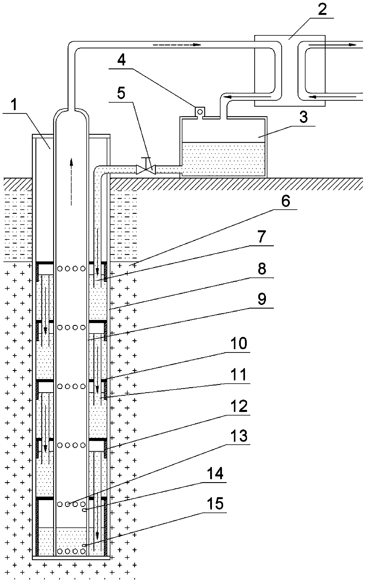
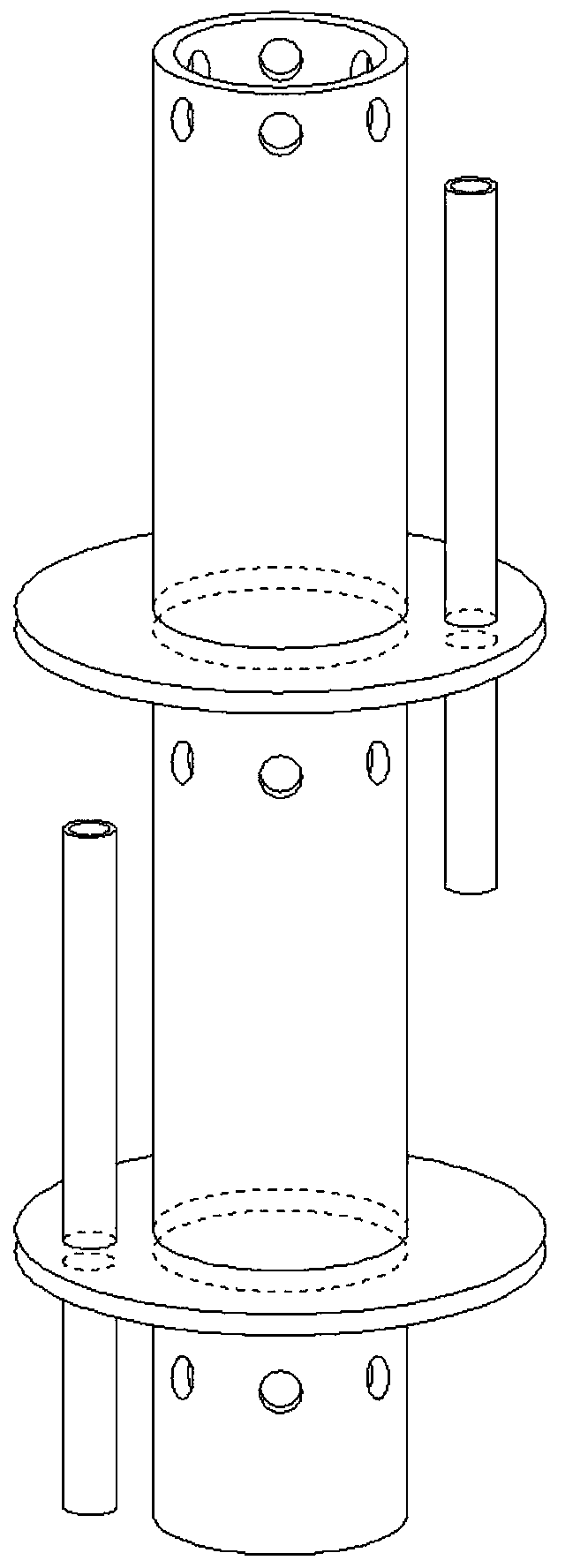
[0022] In this embodiment, the stepped gravity heat pipe geothermal exploitation system without liquid accumulation effect includes a stepped gravity heat pipe 1, a condenser 2 and a liquid storage tank 3; the stepped gravity heat pipe 1 includes a liquid return pipe 7, an outer pipe 8, and an inner pipe 9 The liquid return pipe 7 is located in the gap between the outer pipe 8 and the inner pipe 9 and is connected with the liquid storage tank 3; the steam outlet at the top of the inner pipe 9 is connected with the condenser 2; the condenser 2 exchanges heat with the outside world, and its condensate outlet is connected with the condenser The liquid storage tanks 3 are connected; the liquid working medium in the liquid storage tank 3 re-enters the stepped gravity heat pipe 1 through the liquid return pipe 7 for circulation.

[0023] In the gap...


PUM


Abstract

The invention provides a stepped gravity heat pipe geothermal exploitation system without a liquid accumulation effect. The system comprises a gravity heat pipe, a condenser and a liquid storage tank,wherein the gravity heat pipe comprises a liquid return pipe, an outer pipe and an inner pipe, the liquid return pipe is located in a gap between the outer pipe and the inner pipe and is connected with the liquid storage tank, the gap between the outer pipe and the inner pipe adopts a stepped separation structure, a liquid working medium sequentially flows into the separation sections of all stages from the liquid storage tank through the liquid return pipe, and passes through the pipe wall of the outer pipe to absorb heat from high-temperature rock and then is gasified, and after the liquidworking medium becomes a gaseous working medium, then the gaseous working medium enters the inner pipe again and flows into the condenser, and then flows into the liquid storage tank again for circulation after being subjected to heat release condensation. Compared with the prior art, the heat pipe heat absorption section is designed to be of the stepped separation structure, and the liquid levelof each separation section is limited to a certain height through corresponding liquid level control pipe; and the design can solve the problem that the working medium is difficult to evaporate due toexcessively high liquid level while the heat absorption section is fully wetted, so that the heat transfer efficiency when a super-long heat pipe is used for exploiting the geothermal energy is greatly improved.

Description

technical field [0001] The invention relates to the technical field of geothermal exploitation, in particular to a stepped gravity heat pipe geothermal exploitation system without liquid accumulation effect. Background technique [0002] With the reduction of fossil fuel reserves and the increasingly serious environmental problems brought about by their development and utilization, renewable and non-polluting new energy sources have attracted much attention. Compared with other renewable energy sources, geothermal energy is stable and reliable, and is not affected by factors such as weather, seasons, climate, and diurnal changes, and is more suitable as the basic energy source for heating and power systems. At present, the development and utilization of geothermal resources not only includes direct utilization such as heating and planting, but also can realize geothermal cooling and power generation of medium and high temperature geothermal resources. In addition, the devel...

Claims


Application Information

Patent Timeline
Patent Type & Authority Applications(China)
IPC IPC(8): F24T10/40
CPCF24T10/40Y02E10/10F24T10/17F24T2010/56F28D15/0266F28D15/04F28D2015/0216
Inventor 蒋方明黄文博曹文炅王亦伟
Owner GUANGZHOU INST OF ENERGY CONVERSION - CHINESE ACAD OF SCI
Why Eureka
Try Eureka