Diffracted wave imaging method and device, electronic equipment and storage medium

An imaging method and diffraction wave technology, which can be used in measurement devices, instruments, scientific instruments, etc., to solve problems such as interference or concealment of diffraction imaging.

Active Publication Date: 2019-07-19
CHINA UNIV OF MINING & TECH (BEIJING)
View PDF4 Cites 9 Cited by
  • Summary
  • Abstract
  • Description
  • Claims
  • Application Information

AI Technical Summary

Problems solved by technology

[0003] In the conventional seismic data processing method, since the diffraction wave imaging and the specular reflection wave imaging are integrated, and the energy of the diffraction wave is one to two orders of magnitude weaker than that of the specular reflection wave, the diffraction imaging is often replaced by the specular reflection imaging. Therefore, how to use an effective method to enhance diffraction imaging to generate high-definition diffraction maps is a huge challenge for existing technologies

Method used


Image

  • Diffracted wave imaging method and device, electronic equipment and storage medium
  • Diffracted wave imaging method and device, electronic equipment and storage medium
  • Diffracted wave imaging method and device, electronic equipment and storage medium

Examples


Embodiment 1

[0045] This embodiment provides an inverse polarity inverse phase stabilization filter, through which the inverse polarity inversion phase stabilization filter method realizes the superimposition and enhancement of multiple diffraction waves in the process of diffraction wave imaging, and finally realizes edge diffraction wave imaging with more features high resolution.

[0046] The anti-polarity and anti-phase stabilization filter used for edge diffracted wave imaging provided by this embodiment is expressed as:

[0047]

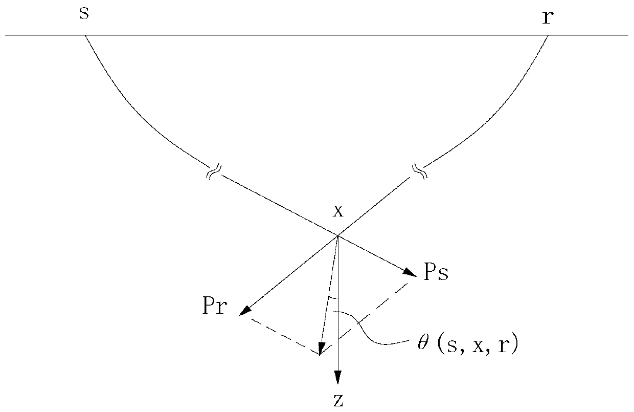
[0048] In the formula, w dp (s,x,r) represent reverse polarity inverting phase stabilization filter, such as image 3 As shown, s is the position of the shot point, x is the position of the imaging point, r is the position of the receiver point; θ 0 (x) is the inclination field, θ 0 (x) represents the dip angle corresponding to the underground geological point, also known as the formation dip angle, θ(s,x,r) is the observation dip angle, θ(s,x,r) refe...

Embodiment 2

[0057] This embodiment provides a diffracted wave imaging method, which utilizes an inverse polarity and anti-stabilized filter to realize the superimposition and enhancement of multiple diffracted waves in the diffracted wave imaging process, and finally realizes edge diffracted wave imaging with higher resolution.

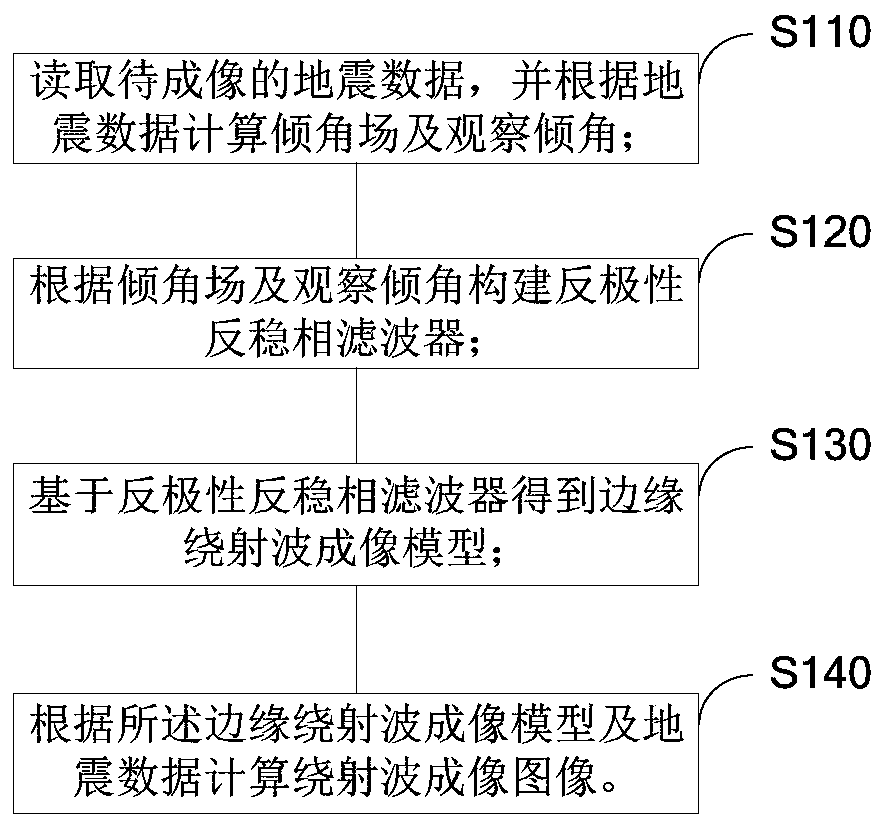
[0058] The diffracted wave imaging method provided in this embodiment, such as figure 1 shown, including the following steps:

[0059] S110: Read the seismic data to be imaged, and calculate the dip field and observe the dip according to the seismic data;

[0060] S120: Constructing an anti-polarity anti-phase stabilization filter according to the inclination field and the observation inclination;

[0061] S130: Obtain an edge diffraction wave imaging model based on an inverse polarity inverse stabilization filter;

[0062] S140: Calculate a diffraction wave imaging image according to the edge diffraction wave imaging model and seismic data.

[0063] This met...

Embodiment 3

[0065] The diffraction wave imaging method provided in this embodiment includes the following steps:

[0066] Read the seismic data U(t',s',r') to be imaged, use the mean filtering method to suppress the noise of the seismic data U(t',s',r') and get U(t,s,r) , where t is the round-trip travel time of the incident ray and the diffracted ray, s is the position of the shot point, and r is the position of the receiver point; the migration profile is obtained based on the Kirchhoff migration method, and the inclination angle estimation method based on plane wave decomposition is used to calculate Get the dip field θ 0 (x);

[0067] The edge diffracted wave imaging model is obtained based on the reverse polarity inverse stable phase filtering method, and the diffracted wave imaging image is calculated according to the edge diffracted wave imaging model. The specific steps include:

[0068] The edge diffraction wave imaging model is obtained based on the reverse polarity and revers...


PUM


Abstract

The invention provides a diffracted wave imaging method and device, electronic equipment and a storage medium, and relates to the technical field of high-resolution imaging in seismic exploration. Themethod comprises the steps of: reading to-be-imaged seismic data and calculating a dip angle field and an observation dip angle according to the seismic data; constructing a reverse-polarity and reverse-stationary phase filter according to the dip angle field and the observation dip angle; obtaining an edge diffracted wave imaging model on the basis of the reverse-polarity and reverse-stationaryphase filter; and calculating a diffracted wave imaging image according to the edge diffracted wave imaging model and the seismic data. Through the method, reflected wave fields can be better suppressed, high-resolution edge diffracted wave imaging results can be obtained, and the positions, faults, breakpoints and coal pinch out points of geological abnormal edge diffracted bodies can be correctly positioned, so as to realize the safe operation of oil/gas migration and coal exploitation.

Description

technical field [0001] The invention relates to the technical field of high-resolution imaging of seismic exploration, in particular to an edge diffraction wave imaging method, device, electronic equipment and storage medium. Background technique [0002] In the field of seismic exploration, seismic data include specular reflection wave field and diffraction wave field. In conventional seismic data processing methods, specular reflection waves are used as effective signals, and diffracted waves are suppressed as noise. With the advancement of oil and gas exploration technology, more and more attention has been paid to local discontinuous geological structures such as faults, collapse columns, pinch-outs, etc. In particular, disasters such as water inrush and gas outburst are all related to local discontinuous geological structures, making diffraction Wave imaging plays a more important role. [0003] In the conventional seismic data processing method, since the diffraction ...

Claims


Application Information

Patent Timeline
Patent Type & Authority Applications(China)
IPC IPC(8): G01V1/36
CPCG01V1/36G01V1/362G01V1/364G01V1/368G01V2210/324G01V2210/51
Inventor 李闯建彭苏萍赵惊涛崔晓芹
Owner CHINA UNIV OF MINING & TECH (BEIJING)
Why Eureka
Try Eureka