Two-dimensional multi-frame modulation and demodulation system

A demodulation system and frame modulation technology, applied in the field of graphic coding, can solve the problems of two-dimensional codes that cannot be dynamically changed for night use, high cost of electronic display screens, and unfavorable promotion, so as to reduce recognition speed and efficiency, increase fault tolerance, The effect of improving the degree of recognition

Pending Publication Date: 2019-07-19
CHONGQING THREE GORGES UNIV
View PDF4 Cites 2 Cited by
  • Summary
  • Abstract
  • Description
  • Claims
  • Application Information

AI Technical Summary

Problems solved by technology

The QR code printed on paper cannot be changed dynamically and it is inconvenient to use at night. Therefore, electronic display screens can only be used to display the QR code
However, the cost of an electronic display is m

Method used


Image

  • Two-dimensional multi-frame modulation and demodulation system
  • Two-dimensional multi-frame modulation and demodulation system
  • Two-dimensional multi-frame modulation and demodulation system

Examples


Embodiment 1

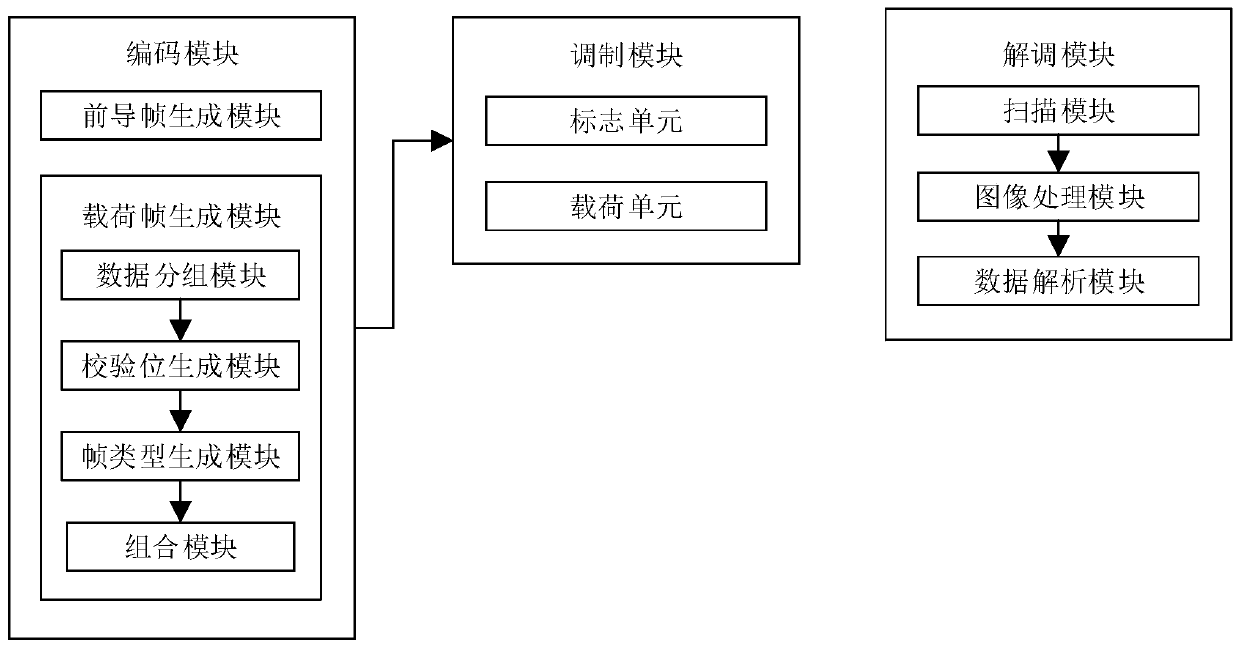
[0030] Such as figure 1 As shown, a two-dimensional multi-frame modulation and demodulation system disclosed in this embodiment includes an encoding module, a modulation module and a demodulation module.

[0031] Wherein, the encoding module is used for encoding the data information input by the information source into a frame sequence composed of multiple data frames, and the data frame includes multiple data bits. Data bits include payload bits, parity bits, and flag bits. The data frame is divided into a leading frame and a payload frame, and the flag bit is used to store frame information. In this embodiment, the frame information is frame type information, including leading frame type, odd frame type and even frame type. The payload bit is used to store data information or configuration information, and the parity bit is used to store the parity information of the data frame. In this embodiment, the data bit of the leading frame stores configuration information, and the ...

Embodiment 2

[0068] The difference between this embodiment and Embodiment 1 is that in this embodiment, the frame type information includes a leading frame and a payload frame, and the payload frame no longer distinguishes odd frames and even frames; the data bits of the leading frame are preset fixed data, In this embodiment, all are 1, and the flag bits of the leading frame and the payload frame are all 1, so that the corresponding modulation unit is in a constant light state; the payload frame adopts the differential modulation mode by default, specifically, the data bits of each frame are the actual The data to be transmitted is XORed with the data bits corresponding to the previous frame; the data bits include payload bits and parity bits. The parity bit is generated according to the data bits of the frame: when the state change of the modulation unit is agreed to be 1, the odd parity is adopted; when the state change of the modulation unit is agreed to be 0, the number of data bits is...

Embodiment 3

[0079] The difference between this embodiment and Embodiment 1 is that in this embodiment, the modulation unit uses red and blue LED lamp beads, and the modulation unit uses the on-off modulation data of the red and blue color components of the lamp bead to modulate 1bit data, each lamp bead can modulate 2bit data. Modulation mode information includes normal mode and differential mode: in normal mode, when the color component of the LED lamp bead is off, the modulated data bit is 0; when the color component of the LED lamp bead is on, the modulated data bit is 0. The bit is 1; in the differential mode, if the on-off state of the color component of the LED lamp bead is the same as that of the previous frame, the modulated data bit is 0, and if it is different from the previous frame, the modulated data bit is 1.

[0080] The difference between this embodiment and Embodiment 1 is that in this embodiment, the data bits of the data frame are divided into payload bits and check dig...


PUM


Abstract

The invention relates to the technical field of graphic coding, and particularly discloses a two-dimensional multi-frame modulation and demodulation system. The system comprises a first controller, aninformation source, a timer, an LED array, an information sink, a second controller and a camera. The information source is electrically connected with an input pin of the first controller. The LED array is electrically connected with an output pin of the first controller. The first controller is used for acquiring data information to be modulated through an information source, and the first controller is used for encoding information source data into a frame sequence formed by a plurality of data frames and controlling the LED array to sequentially modulate the data frames frame by frame. The camera is electrically connected with the signal input end of the second controller. The camera is used for scanning the data frame modulated by the modulation module, and the second controller is used for obtaining image data collected by the camera and processing and analyzing the image to obtain data information. The two-dimensional multi-frame modulation and demodulation system provided by the invention can display the cost of the image code in an electronic mode, and meets the requirement of a user for dynamically changing the image code.

Description

technical field [0001] The invention relates to the technical field of graphic coding, in particular to a two-dimensional multi-frame modulation and demodulation system. Background technique [0002] Graphic coding refers to transforming a certain amount of information into a graphic arrangement according to set rules, that is, information graphics. At present, the most widely used image codes are barcodes and QR codes. With the development of Internet technology, QR codes are used more and more widely. For example, they have important applications in paying transaction money and adding friends in social software. [0003] In some scenarios, the user needs to change the QR code dynamically, for example, different QR codes need to be displayed to different people, or the QR code needs to be changed for security reasons. The QR code printed on paper cannot be changed dynamically and it is inconvenient to use at night. Therefore, electronic display screens can only be used to ...

Claims


Application Information

Patent Timeline
IPC IPC(8): G06K19/06G06K7/10
CPCG06K19/06037G06K7/10821
Inventor 朱丙丽
Owner CHONGQING THREE GORGES UNIV
Why Eureka
Try Eureka