Novel magnetic field modulation type magnetic screw

A magnetic field modulation, magnetic screw technology, applied in the direction of permanent magnet clutch/brake, electric brake/clutch, electrical components, etc., can solve the problems of small output per unit permanent magnet, unsuitable for long-stroke applications, complex structure, etc. Achieve the effect of improving thrust density, simple structure and improving mechanical strength

Inactive Publication Date: 2019-07-19
HARBIN INST OF TECH
View PDF8 Cites 7 Cited by
  • Summary
  • Abstract
  • Description
  • Claims
  • Application Information

AI Technical Summary

Problems solved by technology

[0004] The purpose of the present invention is to solve the problems of the existing magnetic field modulation magnetic lead screw with complex structure, small output per unit permanent magnet, and unsuitability for long-stroke applications. The present invention provides a new type of magnetic field modulation magnetic lead screw

Method used


Image

  • Novel magnetic field modulation type magnetic screw
  • Novel magnetic field modulation type magnetic screw
  • Novel magnetic field modulation type magnetic screw

Examples


Embodiment 1

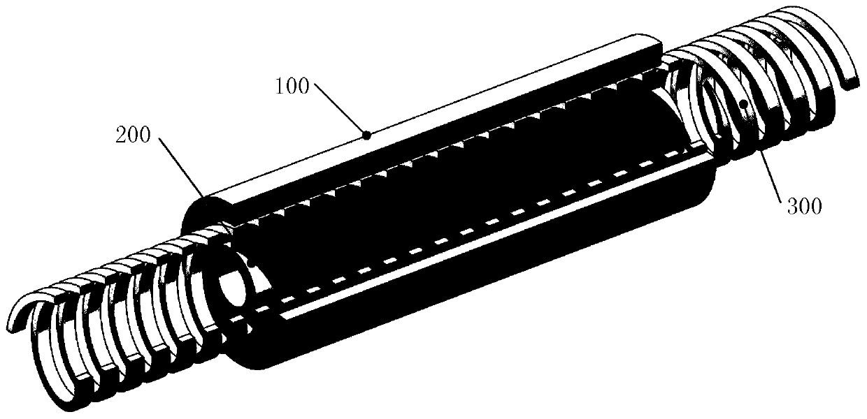
[0049] Embodiment 1: The stator 100 is located outside the helical magnetic ring 300 , and the rotor 200 is inside the helical magnetic ring 300 .

[0050] see figure 1 Describe the specific embodiment 1. The new magnetic field modulation type magnetic lead screw described in this embodiment 1 includes a stator 100, a rotor 200 and a helical magnetic ring 300, and the three are coaxially arranged;

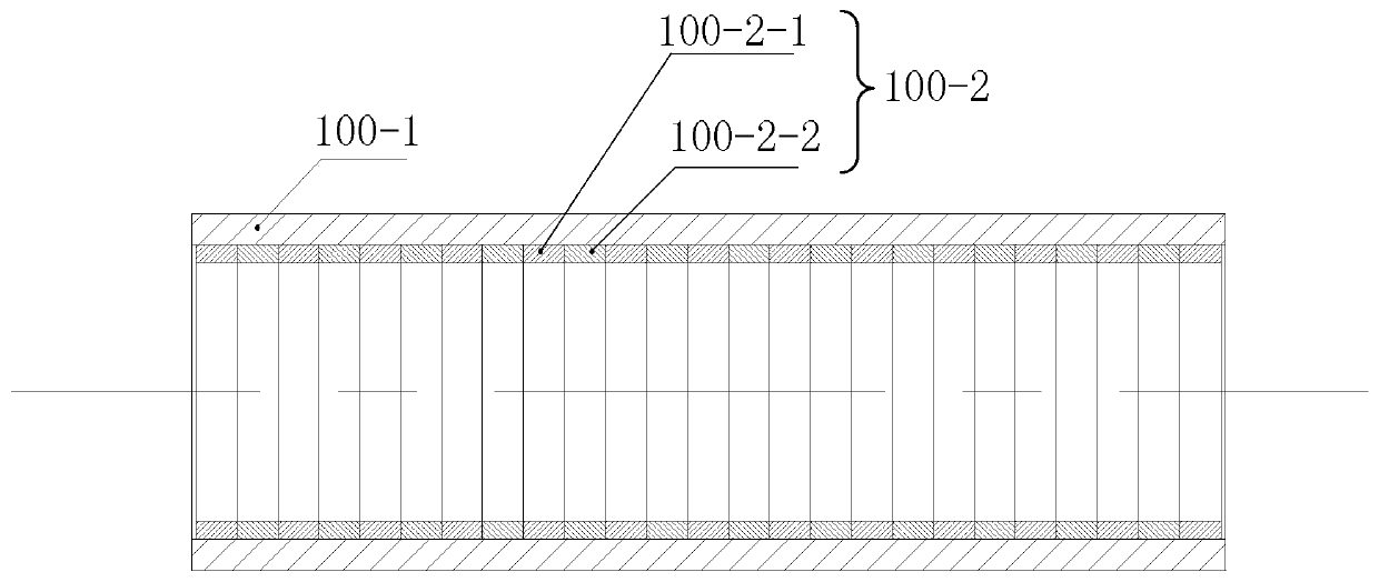
[0051] Both the stator 100 and the rotor 200 are cylindrical structures, and they are arranged opposite to each other;

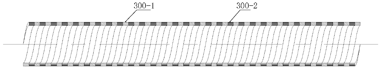
[0052] The helical magnetic ring 300 is located between the stator 100 and the rotor 200, and there is an air gap between the helical magnetic ring 300 and the stator 100 and the rotor 200;

[0053] The stator 100 is located outside the helical magnetic ring 300, and the rotor 200 is inside the helical magnetic ring 300;

[0054] After the rotor 200 is rotated by the external driving force, the helical magnetic field generated by the permanent magnet on the rot...

Embodiment 2

[0075] Embodiment 2: The stator 100 is located inside the helical magnetic ring 300 , and the rotor 200 is outside the helical magnetic ring 300 .

[0076] see Figure 7 Describe specific embodiment 2, the novel magnetic field modulation type magnetic lead screw described in the present embodiment 2, comprises stator 100, rotor 200 and helical magnetic ring 300, and the three are coaxially arranged;

[0077] Both the stator 100 and the rotor 200 are cylindrical structures, and they are arranged opposite to each other;

[0078] The helical magnetic ring 300 is located between the stator 100 and the rotor 200, and there is an air gap between the helical magnetic ring 300 and the stator 100 and the rotor 200;

[0079] The stator 100 is located inside the helical magnetic ring 300, and the rotor 200 is outside the helical magnetic ring 300;

[0080] After the rotor 200 is rotated by the external driving force, the helical magnetic field generated by the permanent magnet on the r...


PUM


Abstract

The invention relates to a novel magnetic field modulation type magnetic screw, belongs to the field of magnetic transmission, and solves the problems that an existing magnetic field modulation type magnetic screw is complex in structure, small in unit permanent magnet output and not suitable for long-stroke application occasions. The magnetic screw comprises a stator, a rotor and a spiral magnetic modulation ring, wherein the stator, the rotor and the spiral magnetic modulation ring are coaxially arranged; the stator and the rotor are of cylindrical structures, and the stator and the rotor are oppositely arranged; the spiral magnetic modulation ring is located between the stator and the rotor, and air gaps are reserved between the spiral magnetic modulation ring and the stator and betweenthe spiral magnetic modulation ring and the rotor; after the rotor is rotated by an external driving force, a spiral magnetic field generated by a permanent magnet on the rotor is adjusted through the spiral magnetic modulation ring, a harmonic magnetic field is generated in the air gap between the spiral magnetic modulation ring and the stator, the harmonic magnetic field interacts with a permanent magnet on the stator to generate an axial thrust, and the axial thrust acts on the spiral magnetic modulation ring, so that the spiral magnetic modulation ring moves linearly in the axial direction. The magnetic screw is mainly applied to the related fields of the magnetic transmission.

Description

technical field [0001] The invention relates to a novel magnetic field modulation type magnetic lead screw, which belongs to the field of magnetic transmission. Background technique [0002] The permanent magnet magnetic screw can realize the mutual transformation of linear motion and rotary motion through magnetic field coupling. It has the advantages of high thrust density, high reliability, and overload protection. It has broad applications in the fields of aerospace, marine power generation, and artificial heart. prospect. However, the traditional permanent magnet magnetic screw is not suitable for long-stroke work, because in large-stroke applications, one of the two parts, the nut and the screw, must have a long axial length, due to the bilateral helical permanent magnets of the magnetic screw Due to structural limitations, the permanent magnets in the non-coupling part are always in an idle state, resulting in a sharp drop in the output of the unit permanent magnets....

Claims


Application Information

Patent Timeline
Patent Type & Authority Applications(China)
IPC IPC(8): H02K49/10
CPCH02K49/102
Inventor 王骞高放李勇江善林刘承军
Owner HARBIN INST OF TECH
Why Eureka
Try Eureka