Centrifugal casting device and method for alloy steel casting and forging

A technology of centrifugal casting and alloy steel, which is applied in the field of centrifugal casting machines. It can solve the problems of large temperature difference between two ends of the casting and uneven hardness at both ends of the casting, and achieve the effects of high casting quality, no temperature drop, and reduced wear.

Inactive Publication Date: 2019-07-23
南通聚星铸锻有限公司
View PDF10 Cites 6 Cited by
  • Summary
  • Abstract
  • Description
  • Claims
  • Application Information

AI Technical Summary

Problems solved by technology

[0004] The object of the present invention is to provide a kind of centrifugal casting equipment and its casting method for alloy steel casting and forging, to solve the above-mentioned background technology. The diversion groove guides the molten steel into the mold cylinder. Since the position of the diversion groove is fixed, the molten steel poured into the mold cylinder can only flow from one end of the mold cylinder to the other end, and the temperature of the molten steel will increase when it flows. gradually decreases, which leads to a large temperature difference between the two ends of the casting, which causes the problem of uneven hardness at both ends of the casting after production.

Method used


Image

  • Centrifugal casting device and method for alloy steel casting and forging
  • Centrifugal casting device and method for alloy steel casting and forging
  • Centrifugal casting device and method for alloy steel casting and forging

Examples


Embodiment Construction

[0027] The following will clearly and completely describe the technical solutions in the embodiments of the present invention with reference to the accompanying drawings in the embodiments of the present invention. Obviously, the described embodiments are only some, not all, embodiments of the present invention. Based on the embodiments of the present invention, all other embodiments obtained by persons of ordinary skill in the art without making creative efforts belong to the protection scope of the present invention.

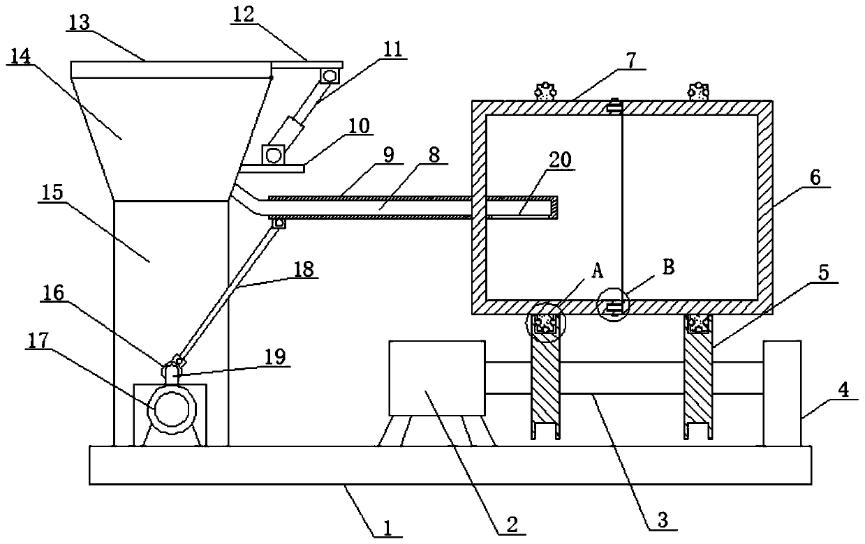
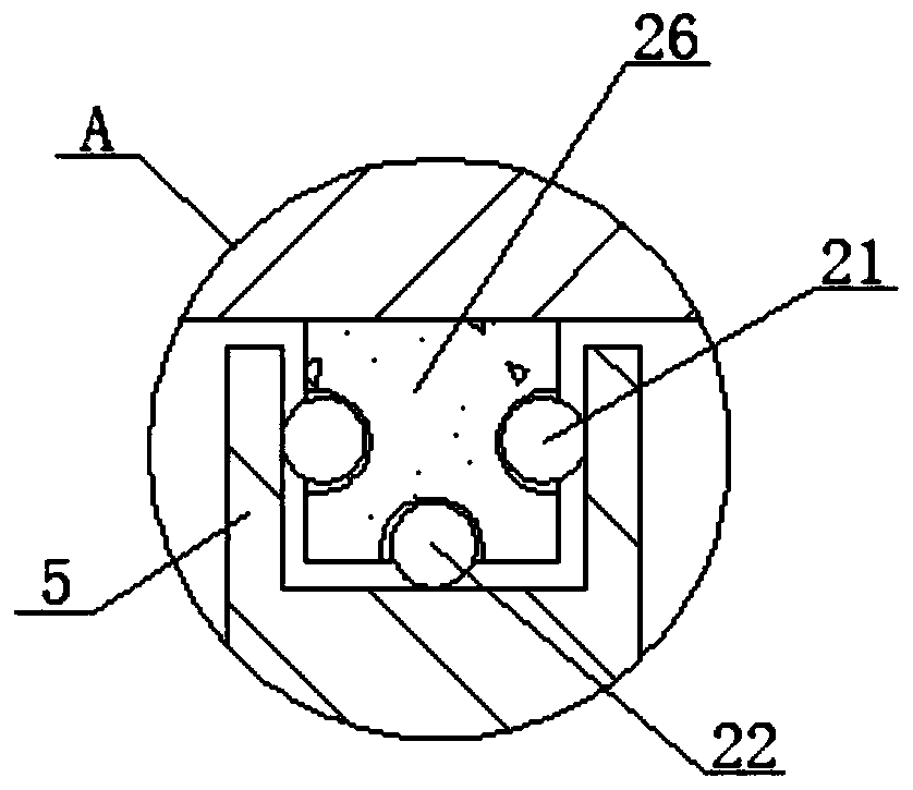
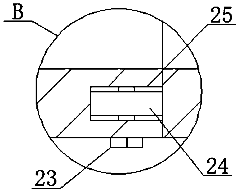
[0028] see Figure 1-4 , the present invention provides a technical solution: a centrifugal casting equipment and casting method for alloy steel casting and forging, including a bottom plate 1, the upper surface of the bottom plate 1 is respectively provided with a mounting frame 15, a second motor 17 and a fixed plate 4, and the upper surface of the base plate 1 is symmetrically provided with first motors 2, the output shaft of each of the first motors 2 is p...


PUM


Abstract

The invention discloses a centrifugal casting device and method for alloy steel casting and forging. The centrifugal casting device comprises a bottom plate, a second centrifugal casting cylinder is arranged in a fixing ring on the left side, a first centrifugal casting cylinder corresponding to the second centrifugal casting cylinder is arranged in a fixing ring on the right side, an output shaftof a second motor is provided with a crankshaft connected with a mounting frame, a sleeve is arranged on the outer side of the crankshaft, an injection hopper is arranged at the top of the mounting frame, a second casting pipe penetrating through the second centrifugal casting cylinder is arranged on the outer side of a first casting pipe, a casting port is arranged on the outer side of a secondcasting pipe, and a connecting rod is arranged between the second casting pipe and the sleeve. The second motor and the crankshaft are arranged, the crankshaft is driven to rotate by starting the second motor, the sleeve on the outer side drives the second casting pipe which is connected with the sleeve through the connecting rod to move leftwards and rightwards, the effect that the casting position is not fixed is achieved, casting is uniform, and casting quality is high.

Description

technical field [0001] The invention belongs to the technical field of centrifugal casting machines, and in particular relates to centrifugal casting equipment and a casting method for alloy steel casting and forging. Background technique [0002] A casting method in which liquid metal is poured into a rotating mold, filled and solidified into a casting under the action of centrifugal force. The machine used for centrifugal casting is called centrifugal casting machine. According to the direction of the rotation axis of the mold, the centrifugal casting machine is divided into three types: horizontal, vertical and inclined. The horizontal centrifugal casting machine is mainly used for casting various tubular castings, such as gray cast iron ductile iron water pipes and gas pipes, with a minimum diameter of 75mm and a maximum diameter of 3000mm. In addition, it can also cast large-diameter copper rollers for paper machines, various Carbon steel, alloy steel pipe, and double...

Claims


Application Information

Patent Timeline
Patent Type & Authority Applications(China)
IPC IPC(8): B22D13/00B22D13/10
CPCB22D13/00B22D13/10B22D13/107
Inventor 归惠清
Owner 南通聚星铸锻有限公司
Why Eureka
Try Eureka