
An automated laser cutting robot device

A technology of laser cutting and robotics, applied in laser welding equipment, metal processing equipment, welding equipment, etc., can solve the problems of object damage, poor quality, melting, etc., and achieve smooth rotation, prevent shaking or sliding, sticking The effect of uniform joint position

Active Publication Date: 2020-03-17
安徽人和智能制造有限公司
View PDF5 Cites 0 Cited by
  • Summary
  • Abstract
  • Description
  • Claims
  • Application Information

AI Technical Summary

Problems solved by technology

[0004] The purpose of the present invention is to solve the problem that the existing laser cutting robot device cuts the object incompletely and incompletely, and after the object is irradiated and cut by laser for a long time, the area that does not need to be cut on the object is easy to be damaged. Melting will cause damage to the object, and the laser cutting robot device can cut the object at the same time when it is working. The miscellaneous dust and debris generated during cutting are not easy to clean up, and the environmental protection of the device is poor. After the laser cutting robot cuts the object, it is difficult for the staff to store and store the object. The burrs generated by cutting cannot be removed in time after being cut, resulting in the problem of poor quality of the cut object, and an automatic laser cutting robot device is proposed

Method used


Image

  • An automated laser cutting robot device
  • An automated laser cutting robot device
  • An automated laser cutting robot device

Examples


Embodiment Construction

[0045] The technical solutions of the present invention will be clearly and completely described below in conjunction with the embodiments. Apparently, the described embodiments are only some of the embodiments of the present invention, not all of them. Based on the embodiments of the present invention, all other embodiments obtained by persons of ordinary skill in the art without creative efforts fall within the protection scope of the present invention.

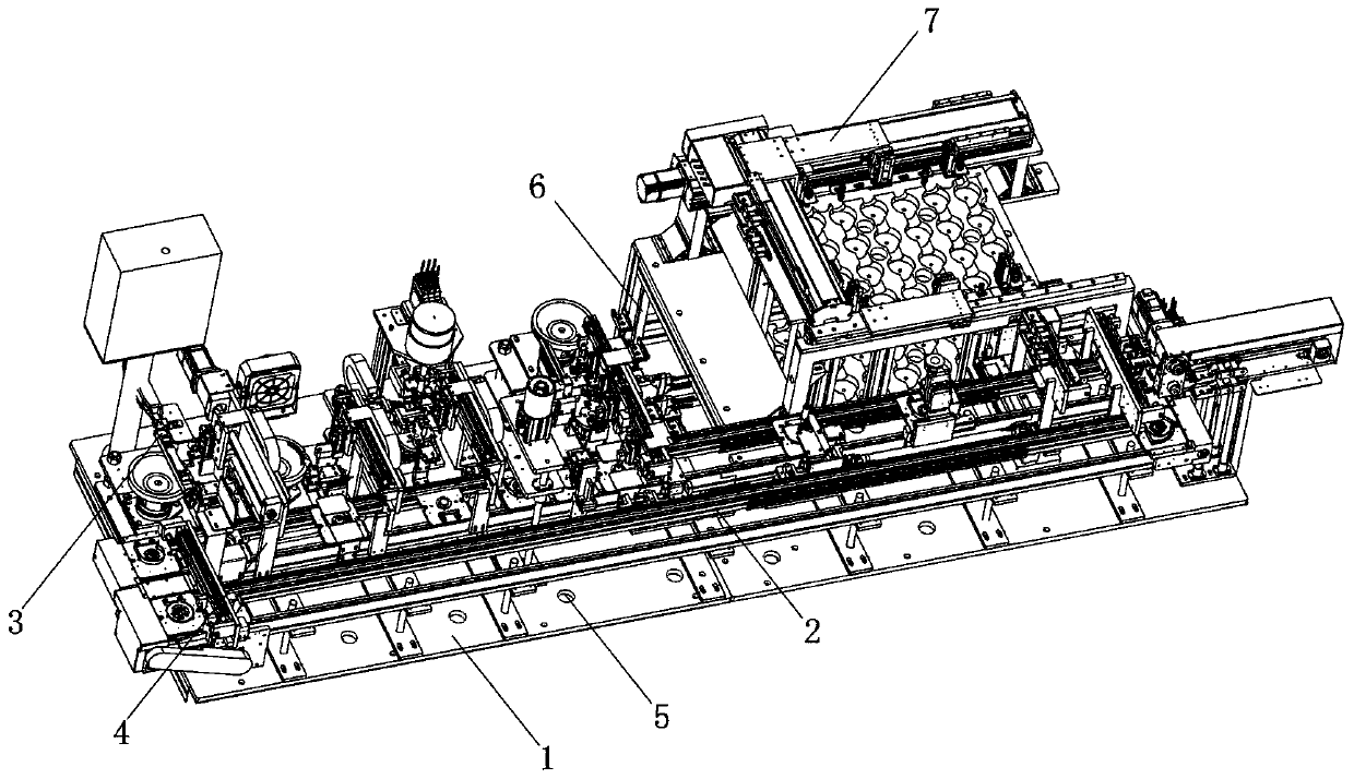
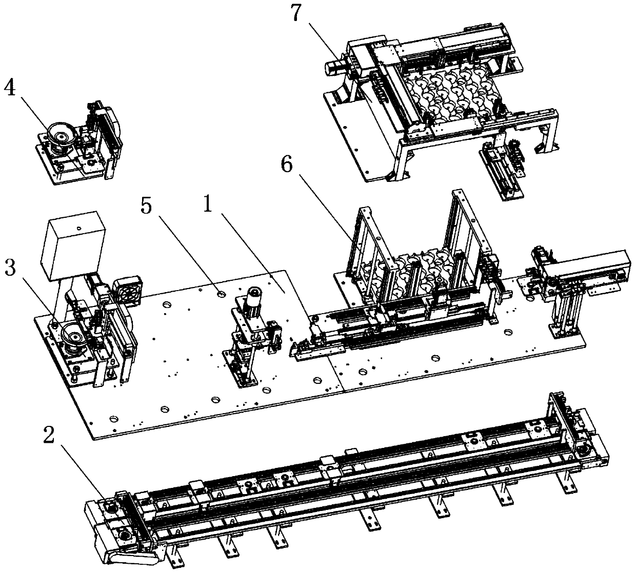
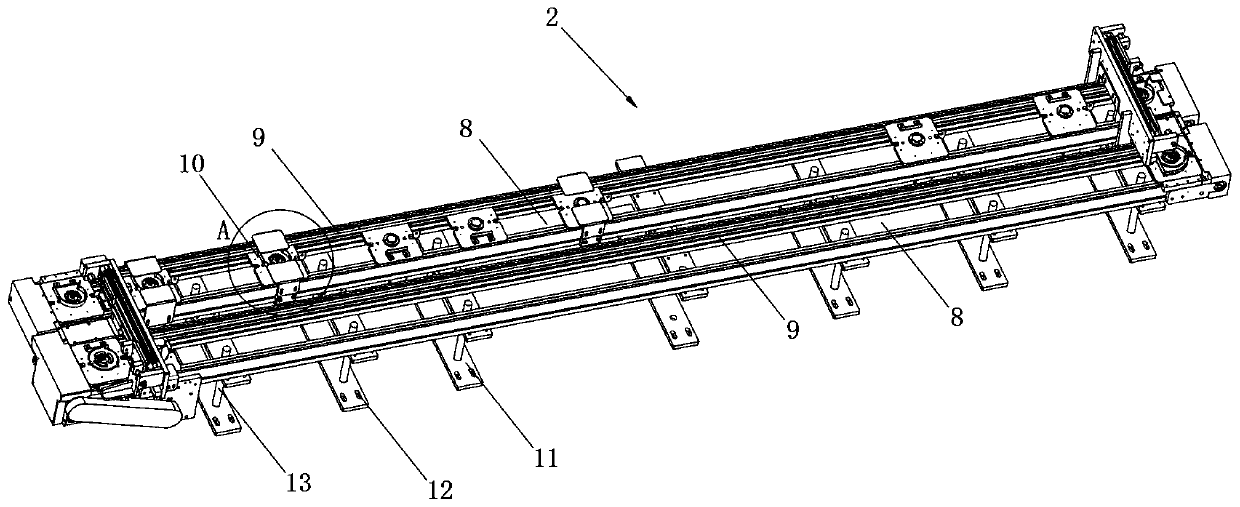
[0046] see Figure 1-8 As shown, an automated laser cutting robot device includes a mounting plate 1, a material transfer table 2, a front cutting disc 3, a rear cutting disc 4, and a storage table 7, and the upper side of the mounting plate 1 is provided with a material transfer table 2, and A front cutting disc 3 is vertically arranged above one end of the material shifting table 2, a rear cutting disc 4 is arranged on one side of the front cutting disc 3, and a storage table 7 is arranged at the other end of the material...


PUM


Abstract

The invention discloses an automatic laser cutting robot device which comprises an installation plate, a material moving table, a front cutting plate, a rear cutting plate and a storage table. The material moving table is arranged on one side above the installation plate, and the front cutting plate is arranged above one end of the material moving table in the vertical direction. The automatic laser cutting robot device has the beneficial effects that a first motor drives a rotary disc and an object to rotate, the cut position is adjusted, and it is ensured that the cutting precision and the cutting efficiency of the object are higher. In addition, grooves are used for being attached to the bottom of the object so that the friction force can be increased, stop blocks in the grooves are matched for clamping and blocking the bottom of the object, and it is ensured that the object is driven to rotate and adjust, and the cutting position is more smooth and firm. Furthermore, the three grooves are arranged in an equal-radian manner, it is ensured that the attaching position and area of the grooves on the bottom of the object are more uniform, it is ensured that the cut object is adjusted and rotated more smoothly, and the object is prevented from jittering or sliding when being adjusted to rotate. The automatic laser cutting robot device is convenient to operate, firm and durable and suitable for use and popularization, and good social benefits are achieved.

Description

technical field [0001] The invention relates to a cutting robot device, in particular to an automatic laser cutting robot device, and belongs to the technical field of laser cutting robot device applications. Background technique [0002] With the rapid development of people's living standards, laser cutting robot devices are used more and more frequently in the cutting and processing of objects in factories, such as metal objects: steel, iron, copper, etc., when processing, laser cutting robot devices are required for cutting and processing , The laser cutting robot device is favored by people because of its high work efficiency, time-saving and labor-saving characteristics. [0003] There are still many deficiencies in the existing laser cutting robot device in use. The existing laser cutting robot device cuts and processes the object incompletely and incompletely, and after the object is irradiated and cut for a long time, It is easy to melt the area that does not need t...

Claims


Application Information

Patent Timeline
IPC IPC(8): B23K26/38B23K26/16B23K26/70
CPCB23K26/16B23K26/38B23K26/702
Inventor 金维国
Owner 安徽人和智能制造有限公司
Learn More