Bottle cap

A technology of bottle caps and sub-caps, applied in the field of bottle caps, can solve the problems of easy contamination, laborious opening and opening of the bottle caps, and inability to adjust the liquid flow rate, etc. Effect

Pending Publication Date: 2019-07-23
徐勇
View PDF0 Cites 3 Cited by
  • Summary
  • Abstract
  • Description
  • Claims
  • Application Information

AI Technical Summary

Problems solved by technology

[0007] Therefore, it is necessary to provide a bottle cap, which is used to overcome the disadvantages of the above-mentioned bottle cap that it is laborious to pull the ope

Method used


Image

  • Bottle cap
  • Bottle cap
  • Bottle cap

Examples


Example Embodiment

[0096] The specific embodiments of the present invention will be further described in detail below with reference to the accompanying drawings.

[0097] For a thorough understanding of the embodiments of the present invention, detailed structures will be presented in the following description. Obviously, the implementation of the embodiments of the present invention is not limited to the special details familiar to those skilled in the art. Preferred embodiments of the present invention are described in detail below, however, the present invention may have other embodiments in addition to these detailed descriptions.

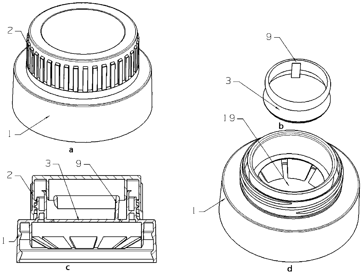
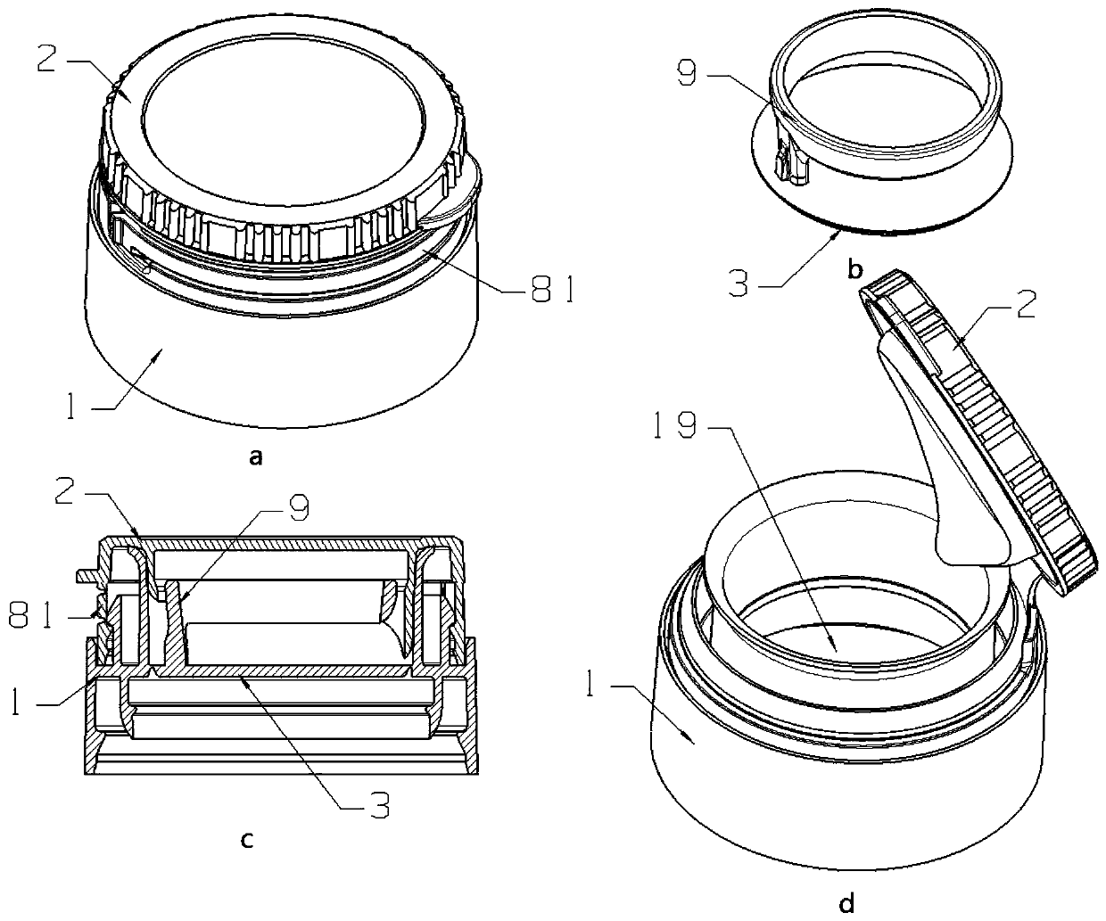
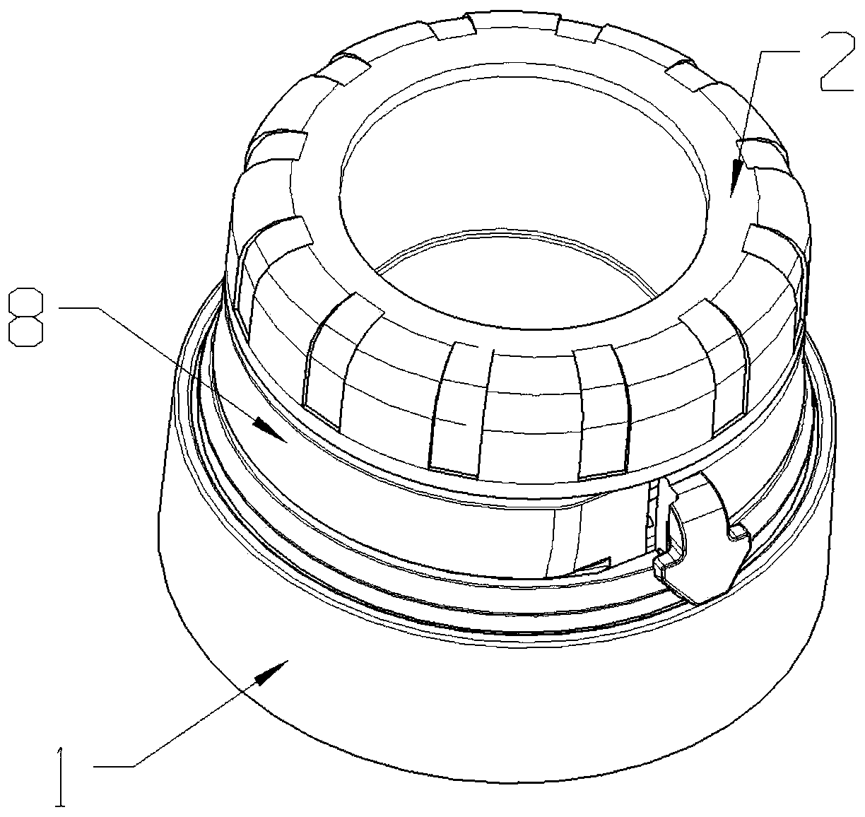
[0098] combine Figure 3-Figure 39 , image 3 It is a schematic diagram of the overall structure of a bottle cap with a high-padded easy-tear ring of the present invention; Figure 4 a is a schematic structural diagram of a main cap of a bottle cap of the present invention provided with protrusions; Figure 4 b is a structural schematic diagram of a bottle c...


PUM


Abstract

The invention discloses a bottle cap. The bottle cap comprises a main cap 1 and an auxiliary cap 2, wherein one or more auxiliary caps 2 are arranged, the main cap 1 and the auxiliary cap 2 are detachably or integrally connected, an opening piece 3 which is integrated with the main cap 1 is arranged on the main cap 1, an impact end 4 is arranged on the auxiliary cap 2, an impacted end 31 is arranged on the opening piece 3, and petal-shaped bodies or strip-shaped bodies are arranged at the upper end or the lower end of the opening piece 3. According to the technical scheme, the structure is very suitable for manufacturing of molds and high-speed production of products, bottle cap opening is simple and labor-saving, liquid can be used without contacting the liquid flowing area in the main cap, the use process is simple and convenient, and the cost is low; and compared with original products, the cost is not increased, and the bottle cap is more sanitary and convenient in use and more suitable for life use.

Description

technical field [0001] The invention belongs to the technical field of packaging containers, in particular to a bottle cap. Background technique [0002] In recent years, with the increasing demand for portability in life, bottle caps have become a very important necessity in the composition of containers required in daily life, such as pull-ring open bottles used in edible oil bottles, seasoning bottles, wine bottles, etc. cover its structure as figure 1 and figure 2 As shown, the bottle cap is composed of a secondary cover 2 and a main cover 1. The main cover 1 is provided with an opening piece 3, and a pull ring 9 is connected to the opening piece. When in use, first break or unscrew the secondary cover 2, or Remove the anti-theft ring 81 on the secondary cover 2 and then open it, hook the pull ring 9 on the main cover with your fingers and pull until the opening piece 3 is pulled away, the opened piece 3 is completely separated from the main cover 1 and becomes waste ...

Claims


Application Information

Patent Timeline
IPC IPC(8): B65D51/18B65D47/20B65D85/72A47J47/01
CPCA47J47/01B65D47/2018B65D51/18B65D85/72
Inventor 徐勇
Owner 徐勇
Why Eureka
Try Eureka