Falling plate connection structure and construction method thereof

A technology for connecting structures and construction methods, which is applied to floors, building components, building structures, etc.

Pending Publication Date: 2019-07-23
CHINA CONSTR STEEL STRUCTURE CORP LTD
View PDF0 Cites 3 Cited by
  • Summary
  • Abstract
  • Description
  • Claims
  • Application Information

AI Technical Summary

Problems solved by technology

[0005] The purpose of the present invention is to provide a connection structure for lowering board

Method used


Image

  • Falling plate connection structure and construction method thereof
  • Falling plate connection structure and construction method thereof
  • Falling plate connection structure and construction method thereof

Examples


Embodiment 1

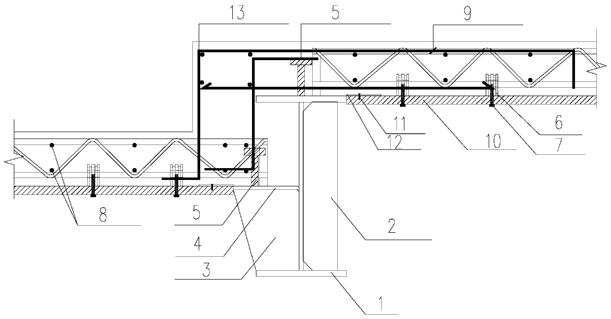
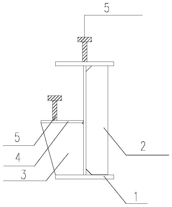
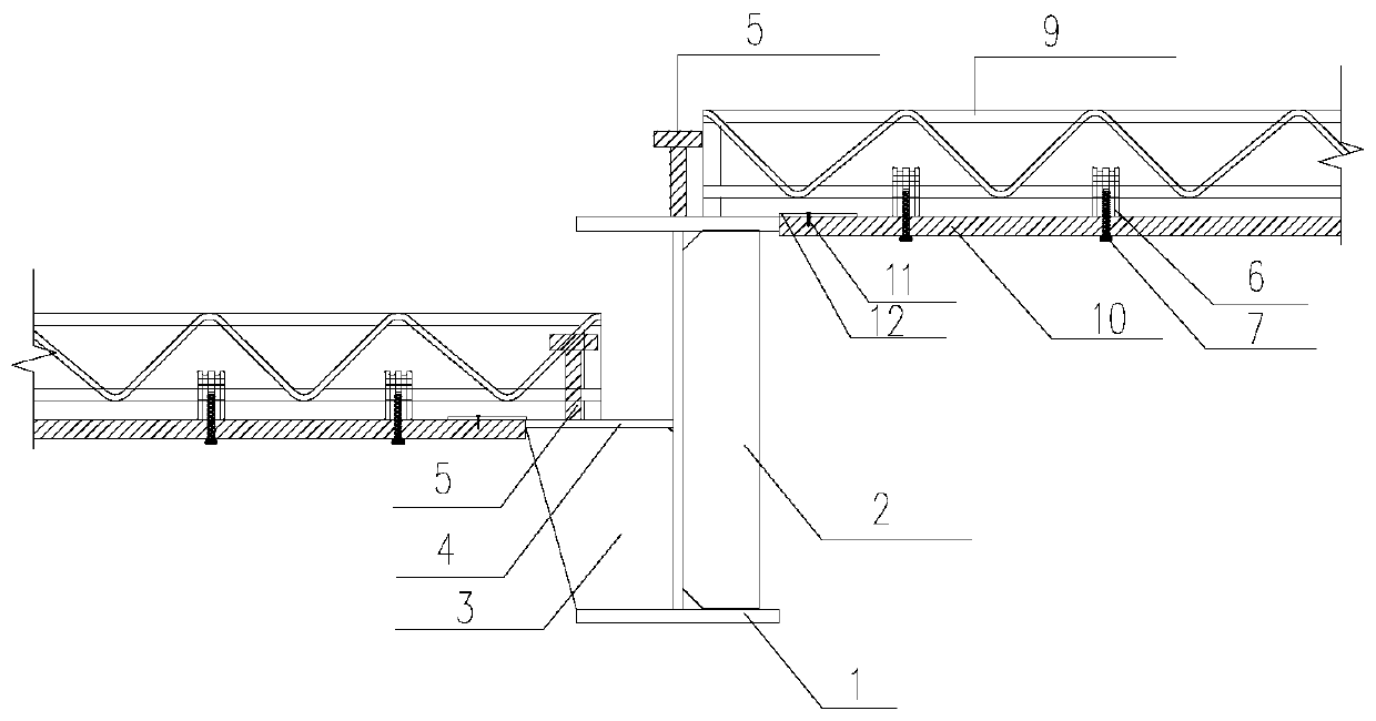
[0035] The lower plate connection structure provided by this embodiment, such as Figure 1 to Figure 4 As shown, the lowering plate connection structure includes a steel beam 1 and a supporting plate 4; the steel beam 1 has a web 2 and an upper flange, and the supporting plate 4 is fixed on the web 2 of the steel beam 1; the upper flange is cast with a The bearing plate on the first floor is poured with the bearing plate on the second floor on the supporting plate 4 .

[0036] Among them, the web 2 is arranged vertically, the upper flange and the web 2 are arranged vertically, the supporting plate 4 and the steel beam 1 can be prefabricated in the workshop, which can not only ensure accurate positioning, but also ensure the welding quality, and directly install the steel beam 1 on site. Finally, the first floor deck is poured on the upper wing plate, and the second floor deck is poured on the supporting plate 4 to form a descending deck connection structure, without redundant ...

Embodiment 2

[0055] The construction method of the lowering plate connection structure provided by the present embodiment comprises the following steps:

[0056] Prefabricate the steel beam 1 and supporting plate 4 provided in Example 1, fix the supporting plate 4 on the web 2 of the steel beam 1, and set the reinforcement 3 between the supporting plate 4 and the web 2;

[0057] The first bottom form 10 is detachably connected to the first truss 9 in advance, and the second bottom form is detachably connected to the second truss;

[0058] Weld studs 5 on the upper wing plate and supporting plate 4 on site, hoist the first truss 9, overlap and weld the first truss 9 on the upper wing plate, and make one end of the first bottom form 10 and the upper edge of the steel beam 1 One end of the wing plate is in contact; the second truss is hoisted, and the second truss is lapped and welded on the supporting plate 4, so that one end of the second bottom form is in contact with one end of the suppor...


PUM


Abstract

The invention provides a falling plate connection structure and a construction method thereof, and relates to the technical field of constructional engineering. The falling plate connection structurecomprises a supporting plate and a steel beam. The supporting plate and the steel beam can be prefabricated in a workshop, the accuracy of positioning can be ensured, the quality of welding can also be ensured, after the steel beam is directly installed on a site, the falling plate connection structure can be formed by pouring a first floor bearing plate on an upper wing plate and pouring a secondfloor bearing plate on the supporting plate, site redundant welding is not required, the construction quality and the construction speed can be ensured, the positioning accuracy and welding quality of components can be ensured, a great deal of welding work on the site can also be avoided, and the quality risk affected by site operation can be reduced.

Description

technical field [0001] The invention relates to the technical field of construction engineering, in particular to a connection structure for lowering slabs and a construction method for the connection structure for lowering slabs. Background technique [0002] With the vigorous development of prefabricated buildings in my country, various new types of prefabricated components are more and more frequently used in various buildings. Compared with traditional forms, the finished product quality, construction quality and construction progress of prefabricated components are easier to control. [0003] In the prior art, the lowering slab joint solves the connection problem of height difference joints during the construction of the floor slab by setting Z-shaped backing plates and additional steel bars at the height of the floor slab. [0004] However, when the height difference exceeds a certain range, when the lowering plate falls to the middle or lower part of the beam, the siz...

Claims


Application Information

Patent Timeline
IPC IPC(8): E04B5/02E04B5/10
CPCE04B5/02E04B5/10
Inventor 胡旭利欧阳超张耀林姜官森周瑜朱德桥汪金祥刘勋
Owner CHINA CONSTR STEEL STRUCTURE CORP LTD
Why Eureka
Try Eureka