Verification device and method for simulating concrete slump form by discrete elements

A verification device and verification method technology, applied in measurement devices, material inspection products, instruments, etc., can solve problems such as lack of devices and methods, and achieve the effect of reasonable quantitative evaluation indicators and accurate results

Active Publication Date: 2019-07-23
SHANGHAI CONSTRUCTION GROUP
View PDF2 Cites 7 Cited by
  • Summary
  • Abstract
  • Description
  • Claims
  • Application Information

AI Technical Summary

Problems solved by technology

There is still a lack of corresponding devices and methods for the ...

Method used


Image

  • Verification device and method for simulating concrete slump form by discrete elements
  • Verification device and method for simulating concrete slump form by discrete elements
  • Verification device and method for simulating concrete slump form by discrete elements

Examples


Embodiment 1

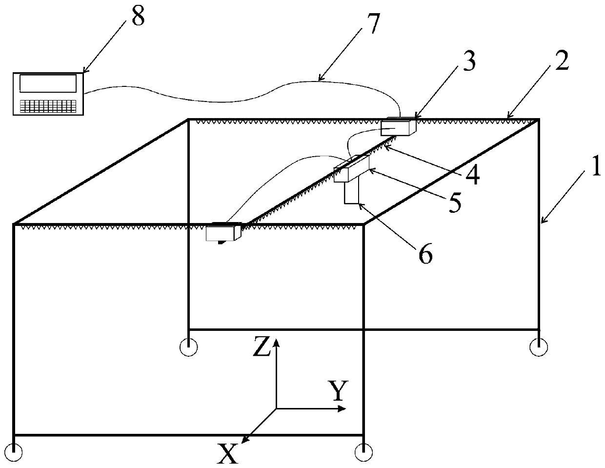
[0044] like figure 1 As shown, a verification device for discrete element simulation of concrete slump form provided in this embodiment is used to measure the surface elevation of concrete after slump, including:

[0045] The support frame 1 is provided with rollers at the bottom;

[0046] A pair of Y-guided rails 2 arranged in parallel, the Y-guided rails 2 are horizontally fixed on the support frame 1, and the Y-guided rails 2 are provided with a driving brake assembly-3;

[0047] The X guide rail 4, the two ends are respectively connected with the drive brake assembly one 3 on the Y guide rail 2 on both sides, and the drive brake assembly two 5 is arranged on the X guide rail 4;

[0048] The rangefinder 6 is arranged below the driving brake assembly 25, and measures the elevation of the measuring point on the surface of the object by a point light source emitted vertically;

[0049] The control terminal 8 includes a control module, a data acquisition and calculation module ...

Embodiment 2

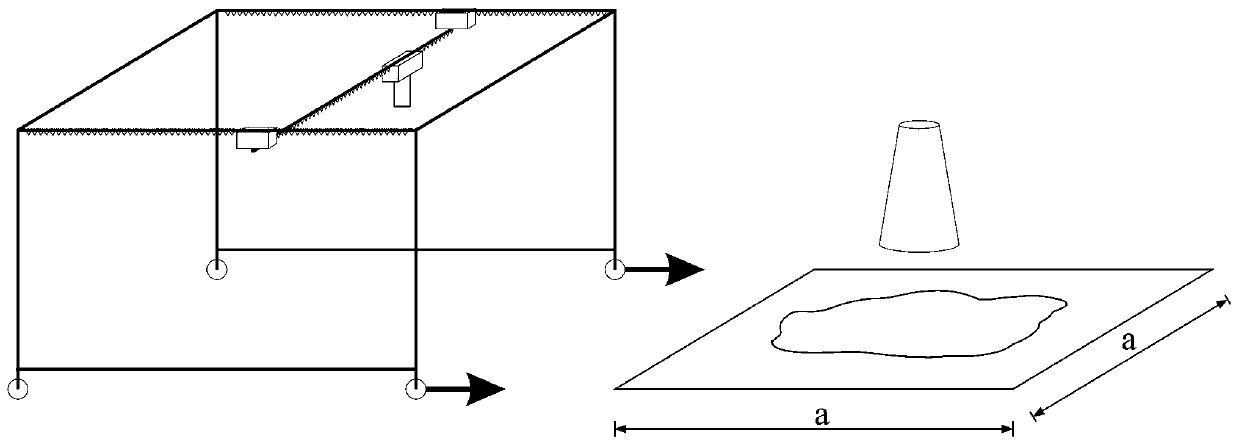
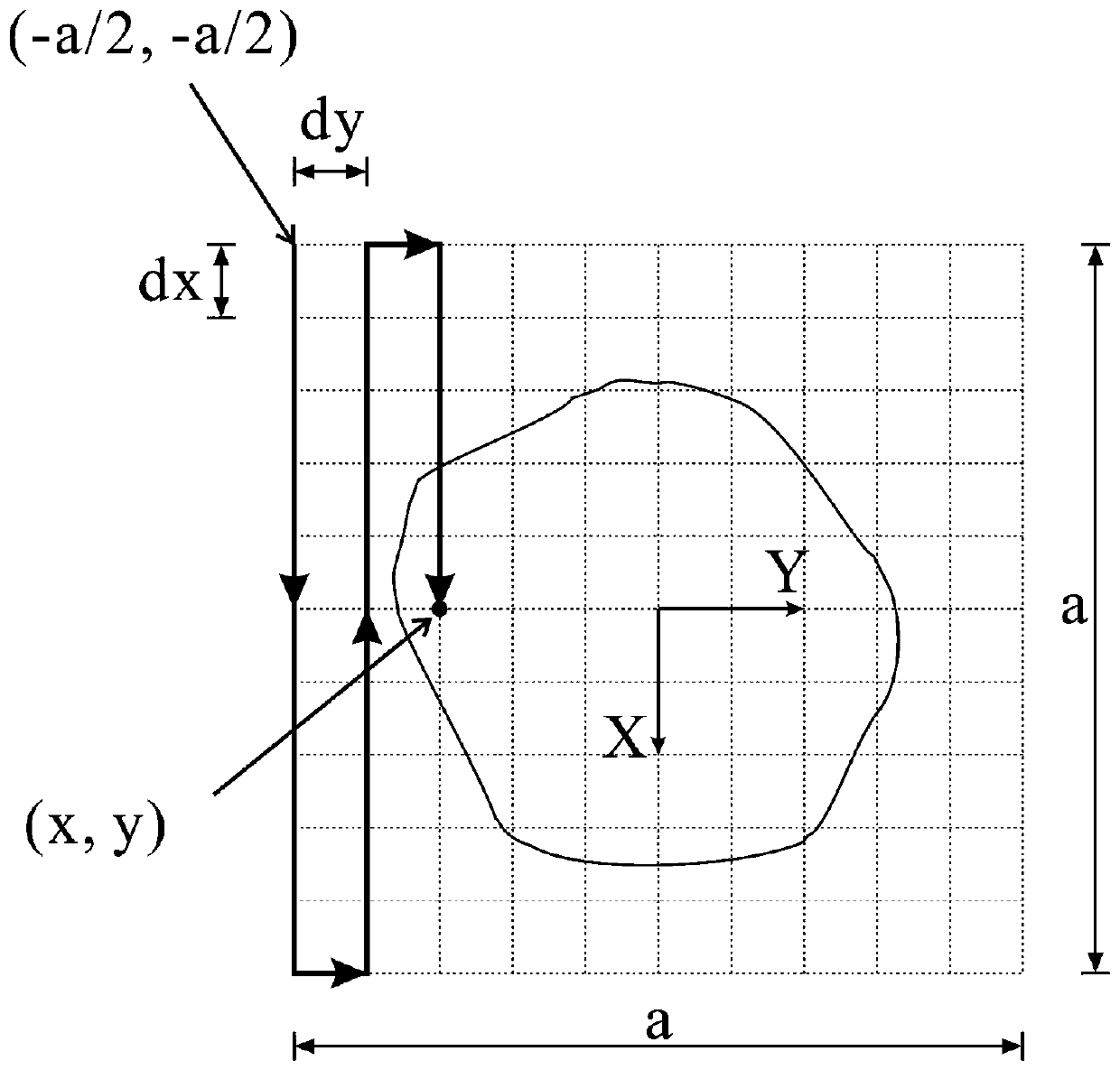
[0054] This embodiment provides a verification method for discrete element simulation of concrete slump form, combined below Figure 1 to Figure 7 This verification method is further introduced. The verification method includes the following steps:

[0055] Step 1: Install the verification device in Embodiment 1 for standby. Such as figure 1 As shown, the verification device includes a support frame 1, a pair of Y guide rails 2 arranged in parallel on the support frame 1, a drive brake assembly 3 arranged on the Y guide rail 2, two ends and a drive The first brake assembly 3 is fixedly connected to the X guide rail 4 , the driving brake assembly 2 5 arranged on the X guide rail 4 , the distance meter 6 and the control terminal 8 arranged under the drive brake assembly 2 5 . Rollers are arranged below the support frame 1 to realize the movement of the support frame 1 . The control terminal 8 includes a control module, a data acquisition and calculation module, and a data pr...


PUM


Abstract

The invention discloses a verification device and method for simulating a concrete slump form by discrete elements, and belongs to the technical field of building material performance detection. The verification device comprises a supporting frame, a pair of Y-direction guide rails arranged on the supporting frame in parallel, a first driving brake assembly arranged on the Y-direction guide rails,an X-direction guide rail of which the two ends are fixedly connected with the first driving brake assembly, a second driving brake assembly arranged on the X-direction guide rail, and a distance measuring instrument arranged below the second driving brake assembly and a control terminal which comprises a control module, a data acquisition and calculation module and a data processing module. According to the verification device and method, by measuring the distance of a surface measuring point after the concrete slump, calculating the three-dimensional coordinate of the measuring point, converting the three-dimensional coordinate of the measuring point into a polar coordinate, fitting the polar coordinate into a longitudinal section diagram of the concrete slump form simulated by discreteelements, the concrete slump form simulated by the discrete elements is verified, and a quantitative evaluation index has the reasonability.

Description

technical field [0001] The invention relates to a verification device and method for simulating concrete slump form with discrete elements, and belongs to the technical field of building material performance detection. Background technique [0002] Concrete is one of the most important engineering construction materials. The working performance of fresh concrete is an important factor affecting the efficiency and quality of construction. Accurate measurement of the properties of concrete mixture is the prerequisite for analyzing and predicting the flow behavior of concrete and construction performance. Concrete slump tests are usually required in the study of concrete performance. Generally speaking, in the slump test, people only use a straightedge to measure the slump value of the concrete in the vertical direction and the expansion value of the concrete in the horizontal direction after the slump. [0003] With the deepening of research, scholars began to study the detai...

Claims


Application Information

Patent Timeline
IPC IPC(8): G06F17/50G01B21/20G01N33/38
CPCG01N33/383G01B21/20G06F30/20Y02E30/30
Inventor 占羿箭黄玉林左自波潘曦陈东杜晓燕
Owner SHANGHAI CONSTRUCTION GROUP
Why Eureka
Try Eureka