Rotor structure and design method of a permanent magnet assisted synchronous reluctance motor

A rotor structure and auxiliary synchronization technology, which is applied in the direction of magnetic circuit shape/style/structure, magnetic circuit rotating parts, magnetic circuit, etc., can solve the problem of large torque pulsation, reduce torque pulsation, and optimize air gap The effect of magnetic density waveform and wide operating speed range

Active Publication Date: 2020-09-25
DALIAN UNIV OF TECH
View PDF8 Cites 3 Cited by
  • Summary
  • Abstract
  • Description
  • Claims
  • Application Information

AI Technical Summary

Problems solved by technology

[0005] The purpose of the present invention is to propose a rotor structure and design method of a permanent magnet assisted synchronous reluctance motor to solve the problem of large torque ripple during the operation of the existing permanent magnet assisted synchronous reluctance motor, improve the control accuracy of the motor, In order to achieve the smooth and efficient operation of the motor, it can be better applied to the electric drive system

Method used


Image

  • Rotor structure and design method of a permanent magnet assisted synchronous reluctance motor
  • Rotor structure and design method of a permanent magnet assisted synchronous reluctance motor
  • Rotor structure and design method of a permanent magnet assisted synchronous reluctance motor

Examples


Embodiment Construction

[0025] In order to make the content of the present invention more clearly understood, the present invention will be further described in detail below based on specific embodiments and in conjunction with the accompanying drawings.

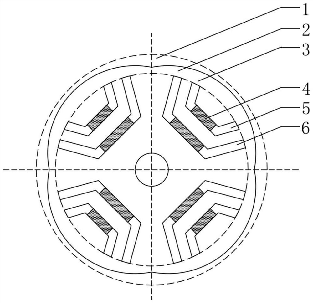
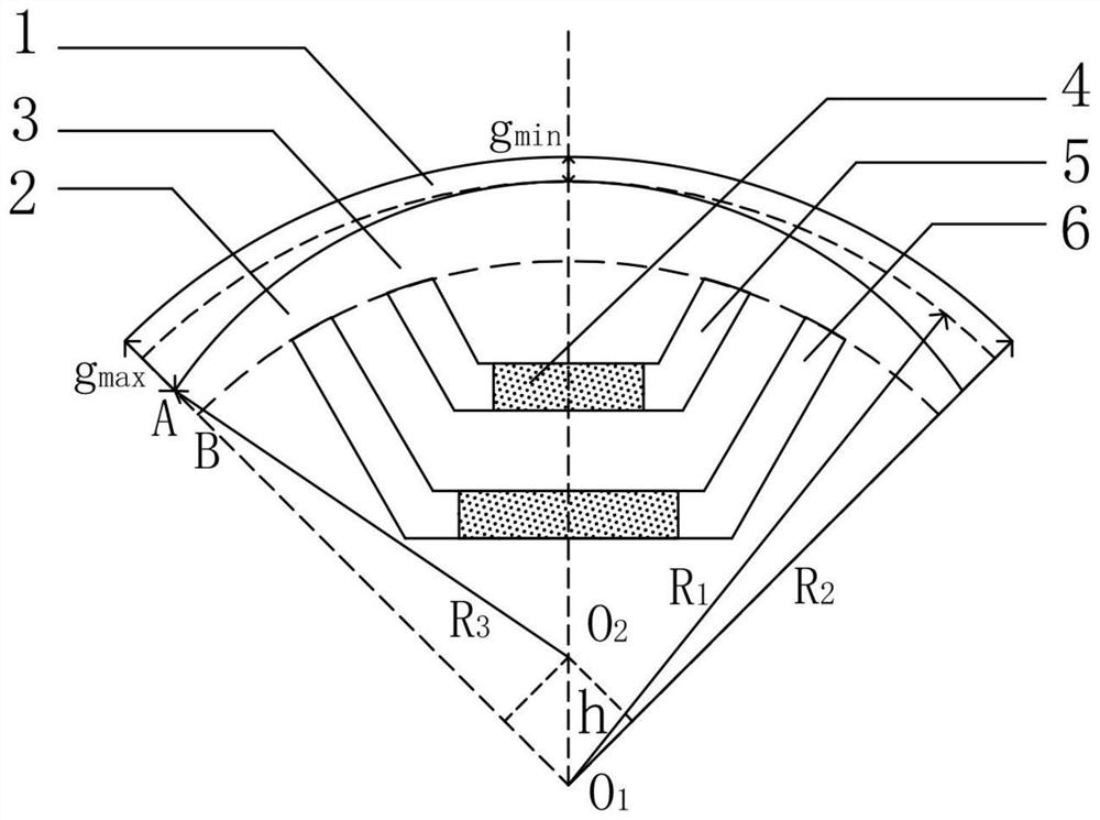
[0026] The traditional permanent magnet motor is a 4-pole 36-slot permanent magnet-assisted synchronous reluctance motor, and the inner diameter of the motor stator is R 2 =162mm, rotor outer diameter R 1 =160.4mm, the motor air gap length is g=1.6mm, and the magnetic bridge width is bg0=2mm.

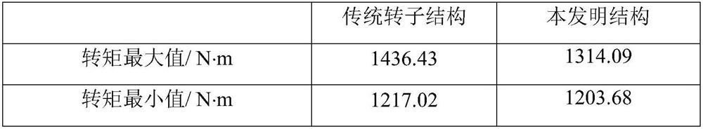
[0027] When the motor adopts the traditional uniform air gap plus equal width magnetic bridge structure, the stator winding is fed with a current of 190A, and under the condition that the internal power factor angle = 60°, the maximum value of the electromagnetic torque is 1436.43N·m, and the minimum value is 1217.02N·m, the average torque is 1339.12N·m, and the torque ripple is as high as 16.38%.

[0028] Such as figure 1 with figure 2 As shown, the pe...


PUM


Abstract

The invention belongs to the technical field of permanent magnet motors and relates to a rotor structure of a permanent magnet auxiliary synchronous reluctance motor and a design method. The rotor structure comprises a rotating shaft, a rotor iron core and a permanent magnet block; the rotor iron core is provided with a central hole, and the rotary shaft penetrates through the central hole of therotor iron core and is fixedly connected with the rotor iron core; the rotor iron core is evenly divided into an even number of poles, and at least two layers of U-shaped magnetic barriers are arranged in each pole. The distance between the circle center O1 of an outer circle formed by the U-shaped magnetic barriers in each pole and the circle center O2 of the outer circle of the rotor iron core is h, and h is larger than 0; and a magnetic pole center line formed by the U-shaped magnetic barriers in each pole passes through the circle center O1 and the circle center O2. Therefore, a non-uniform air gap and non-equal-width magnetic bridge rotor structure is constructed. According to the rotor structure and the design method in the invention, the sine degree of air gap flux density in the motor is improved, the air gap flux density waveform is optimized, the problem of torque ripple of the permanent magnet auxiliary synchronous reluctance motor is solved, the torque ripple is obviously reduced, and the motor can be guaranteed to run more stably and efficiently in an electric transmission system.

Description

technical field [0001] The invention belongs to the technical field of permanent magnet motors, and relates to a rotor structure and a design method of a permanent magnet assisted synchronous reluctance motor. Background technique [0002] At present, asynchronous motor systems are mostly used in the field of electrical transmission. Compared with asynchronous motor systems, permanent magnet motor systems have the characteristics of low loss and high efficiency, which is the development trend of the next generation of transmission systems. Due to the high back electromotive force of ordinary permanent magnet synchronous motors, there is a danger of damaging the inverter during high-speed operation, so permanent magnet assisted synchronous reluctance motors are favored. [0003] The permanent magnet assisted synchronous reluctance motor has the characteristics of both the permanent magnet synchronous motor and the synchronous reluctance motor. In addition to the significant a...

Claims


Application Information

Patent Timeline
Patent Type & Authority Patents(China)
IPC IPC(8): H02K1/27
CPCH02K1/272
Inventor 孙建忠王艳超白凤仙
Owner DALIAN UNIV OF TECH
Why Eureka
Try Eureka