Supercharge Your Innovation With Domain-Expert AI Agents!

Photoelectric conversion module frequency response automatic measurement device and method

A photoelectric conversion module, frequency response technology, applied in the direction of measuring device, measuring electricity, measuring electrical variables, etc., can solve the problems of repeated calibration, low efficiency, lower skill requirements, etc., to meet the measurement needs, low skill requirements, lower skills desired effect

Inactive Publication Date: 2019-07-26
青岛兴仪电子设备有限责任公司 +1
View PDF10 Cites 4 Cited by
  • Summary
  • Abstract
  • Description
  • Claims
  • Application Information

AI Technical Summary

Problems solved by technology

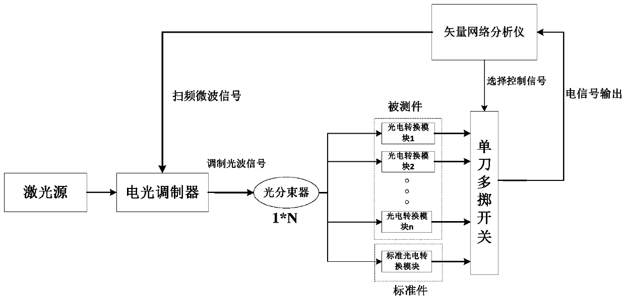
[0005] In order to solve the frequency response parameter measurement of batch photoelectric conversion modules in the production line, solve the problems of batch module testing one by one, frequency point testing, repeated calibration, and low efficiency, the first aspect of the present disclosure provides a photoelectric conversion module frequency response automatic The measuring device is completely suitable for frequency response measurement of batches of photoelectric conversion modules. When it is necessary to replace the DUT, it is not necessary to perform electrical calibration and optical path calibration again, eliminating the cumbersome steps of frequently plugging and unplugging cables; it can completely realize photoelectric conversion. The automatic measurement and data storage of the conversion module eliminates the need for operator comparison analysis and calculation, which greatly reduces the skill requirements of the operator during the measurement process

Method used


Image

  • Photoelectric conversion module frequency response automatic measurement device and method
  • Photoelectric conversion module frequency response automatic measurement device and method

Examples


Embodiment Construction

[0024] The present disclosure will be further described below in conjunction with the accompanying drawings and embodiments.

[0025] It should be noted that the following detailed description is exemplary and intended to provide further explanation of the present disclosure. Unless defined otherwise, all technical and scientific terms used herein have the same meaning as commonly understood by one of ordinary skill in the art to which this disclosure belongs.

[0026] It should be noted that the terminology used herein is only for describing specific embodiments, and is not intended to limit the exemplary embodiments according to the present disclosure. As used herein, unless the context clearly dictates otherwise, the singular is intended to include the plural, and it should also be understood that when the terms "comprising" and / or "comprising" are used in this specification, they mean There are features, steps, operations, means, components and / or combinations thereof.

...


PUM


Abstract

The invention provides a photoelectric conversion module frequency response automatic measurement device and a method, wherein the photoelectric conversion module frequency response automatic measurement device comprises a laser source, a photoelectric modulator, a 1*N optical beam splitter and a single pole multi-throw switch, wherein the laser source is used for providing continuous optical waves for the photoelectric modulator; the photoelectric modulator is used for modulating the continuous optical waves into a strength modulation optical wave signal in the same frequency with a microwavemodulation signal; the 1*N optical beam splitter is used for performing power distribution for the strength modulation optical wave signal, wherein one path is input into a standard component, and other paths are correspondingly input into each to-be-measured photoelectric conversion module; a vector network analyzer is used for controlling the single pole multi-throw switch to respectively gateelectric signal output of the standard component and each to-be-measured photoelectric conversion module, thus, the current frequency response of the laser source can be obtained through calculation;then, a general frequency response parameter is measured, thus, the frequency response of the to-be-measured photoelectric conversion module of each path can be solved, wherein the frequency responsesof the photoelectric modulator, the 1*N optical beam splitter, the single pole multi-throw switch and the standard component are all known parameters.

Description

technical field [0001] The disclosure belongs to the field of photoelectric detection, and in particular relates to a device and method for automatically measuring the frequency response of a photoelectric conversion module. Background technique [0002] The statements in this section merely provide background information related to the present disclosure and do not necessarily constitute prior art. [0003] The photoelectric conversion module mainly completes the photoelectric conversion of the modulated light wave test signal. It is an important part of the optical receiver of the optical fiber communication system and the frequency response parameter test of photoelectric devices. Its frequency response, group delay and other parameters are important to measure the performance. Therefore, in the process of developing and producing photoelectric conversion modules, it is necessary to strictly test its frequency response and other parameters. [0004] The inventors found t...

Claims


Application Information

Patent Timeline
Patent Type & Authority Applications(China)
IPC IPC(8): G01M11/00G01R31/01
CPCG01M11/00G01R31/01
Inventor 韩顺利鞠军委金辉曲天阳刘加庆
Owner 青岛兴仪电子设备有限责任公司
Features
  • R&D
  • Intellectual Property
  • Life Sciences
  • Materials
  • Tech Scout
  • Unparalleled Data Quality
  • Higher Quality Content
  • 60% Fewer Hallucinations
Learn More