Horizontal shear wave energy converter used for coarse grain material welding line detection

A horizontal shear wave and weld detection technology, which is applied in the analysis of materials, the use of sound waves/ultrasonic waves/infrasonic waves for material analysis, and the use of sound waves/ultrasonic waves/infrasonic waves to analyze solids, etc., can solve problems such as inability to detect weld seams, and achieve results Accurate, high detection accuracy, precise defect location effect

Pending Publication Date: 2019-07-26
SHANGHAI INST OF SPECIAL EQUIP INSPECTION & TECHN RES
View PDF13 Cites 2 Cited by
  • Summary
  • Abstract
  • Description
  • Claims
  • Application Information

AI Technical Summary

Problems solved by technology

However, the above-mentioned patented technology and the common horizontal shear wave excited by magnetostriction are not obliquely incident, so it is impossible to detect the weld seam

Method used


Image

  • Horizontal shear wave energy converter used for coarse grain material welding line detection
  • Horizontal shear wave energy converter used for coarse grain material welding line detection
  • Horizontal shear wave energy converter used for coarse grain material welding line detection

Examples


Embodiment 1

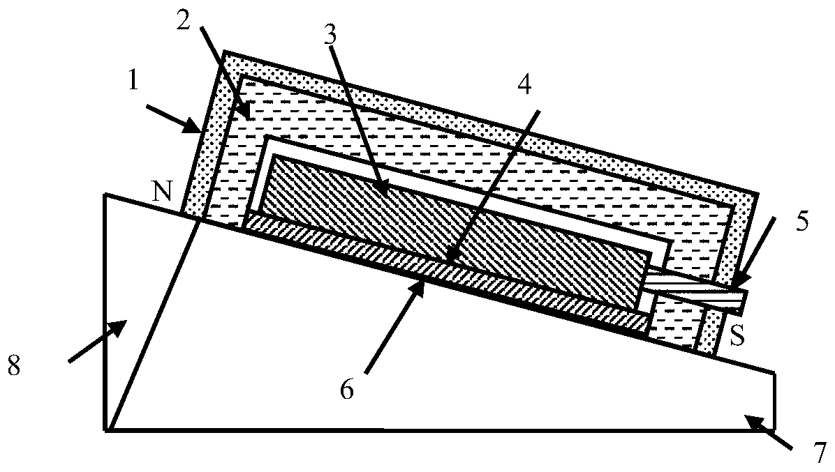
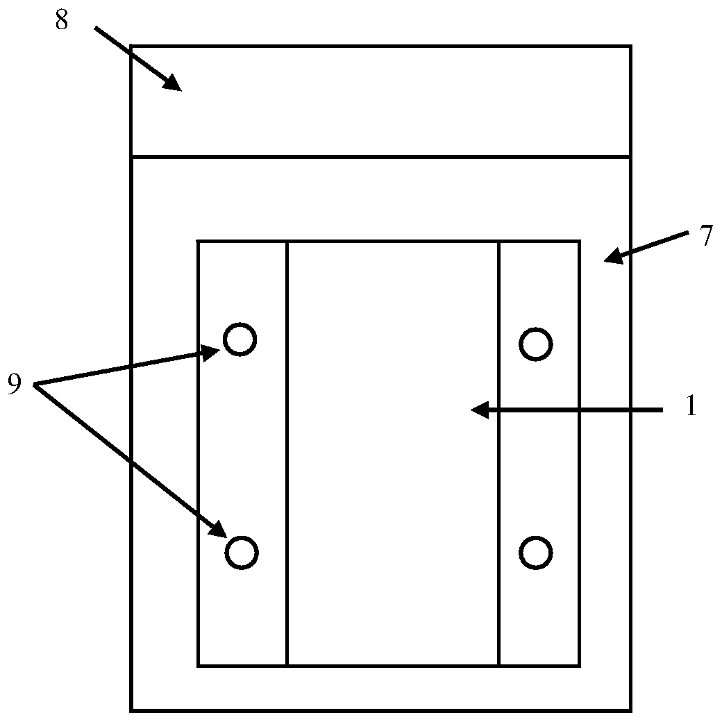
[0038] A horizontal shear wave transducer for the inspection of welds in coarse-grained materials such as figure 1 As shown, it includes a transducer body, a shell 1 for encapsulating the transducer body, a wedge 7 for carrying the transducer body, and a sound-absorbing layer 8 connected to the end of the wedge 7 . Wherein, the transducer body includes a permanent magnet 2 placed on the slope of the wedge 7, a magnetic induction coil 3 placed inside the permanent magnet 2, a magnetic induction sheet 4 attached to the lower surface of the magnetic induction coil 3, and a magnetic induction sheet 4 attached to the magnetic induction sheet 4. The epoxy resin coupling layer 6 on the lower surface, and the signal line connector 5 connected with the magnetic induction coil 3 .

[0039] The functions of each part in this embodiment are: the shell 1 is used to encapsulate the transducer body structure; the permanent magnet 2 is used to generate a horizontal bias magnetic field; wave ...

Embodiment 2

[0045] The main structure of this embodiment is the same as that of Embodiment 1, the difference lies in the design parameters of the wedge and the internal parts of the transducer body. In this embodiment, the angle between the inclined plane and the bottom surface of the wedge used is 60°; meanwhile, the width of the magnetic induction sheet 4 is 25 mm; the thickness of the magnetic induction sheet 4 is 0.2 mm, and the number of turns of the magnetic induction coil 3 is 40 turns , the signal line connector 5 matched with the magnetic induction coil 3 is an interface with 20 pins.

Embodiment 3

[0047] The main structure of this embodiment is the same as that of Embodiment 1, the difference lies in the design parameters of the wedge and the internal parts of the transducer body. In the present embodiment, the angle between the inclined plane and the bottom surface of the wedge used is 70°; meanwhile, the width of the magnetic induction sheet 4 is 50 mm; the thickness of the magnetic induction sheet 4 is 0.25 mm, and the number of turns of the magnetic induction coil 3 is 100 turns , the signal line connector 5 matched with the magnetic induction coil 3 is an interface with 40 pins.


PUM

PropertyMeasurementUnit
widthaaaaaaaaaa
thicknessaaaaaaaaaa
widthaaaaaaaaaa

Abstract

The invention relates to a horizontal shear wave energy converter used for coarse grain material welding line detection. The energy converter comprises an energy converter, a shell used for packagingthe energy converter body, a wedge block used for bearing the energy converter body, and a sound adsorption layer used for connecting to the end part of the wedge block, wherein the wedge block is adopted to spread the horizontal shear wave into the welding line at a certain angle, and the sound adsorption layer is adopted to eliminate residual sound waves in the wedge block. Compared with the prior art, the horizontal shear wave energy converter has the advantages of simple structure, accurate detection result, convenience in use and installation and the like.

Description

technical field [0001] The invention relates to a guided wave transducer, in particular to a horizontal shear wave transducer used for detecting weld seams of coarse-grained materials. Background technique [0002] The horizontal shear wave is a transverse wave in which the vibration direction of the particle is parallel to the surface of the workpiece. When traditional ultrasound detects welds of coarse-grained materials, due to the coarse grains of the welds, the propagation direction of the sound waves will be changed and a large number of clutter signals will be generated. Because the vibration direction of the horizontal shear wave is different from that of the shear wave, it is less affected by the coarse-grained material, and it is an ideal waveform for detecting the weld of the coarse-grained material. [0003] Chinese patent CN106093209A discloses a magnetostrictive phased array horizontal shear guided wave transducer. Multiple magnetostrictive sheet array elements...

Claims


Application Information

Patent Timeline
Patent Type & Authority Applications(China)
IPC IPC(8): G01N29/04G01N29/24G01N29/22
CPCG01N29/043G01N29/2412G01N29/22G01N2291/0234G01N2291/267
Inventor 刘书宏朱旭晨丁菊
Owner SHANGHAI INST OF SPECIAL EQUIP INSPECTION & TECHN RES
Why Eureka
Try Eureka