Analysis system and method for camera and projector calibration

An analysis system and projector technology, which is applied in the field of analysis systems, can solve problems such as image distortion, low model precision, and inconvenient calibration, and achieve the effect of high precision and model fidelity

Active Publication Date: 2019-07-26
盎维云(深圳)计算有限公司
View PDF4 Cites 3 Cited by
  • Summary
  • Abstract
  • Description
  • Claims
  • Application Information

AI Technical Summary

Problems solved by technology

[0005] The technical problem to be solved by the present invention is to overcome the inconvenient calibration, serious image distortion, and low precision of model establishment in the prior art in the grating projection for 3D reconstruction to provide a more accurate way to obtain the calibration rel...

Method used


Image

  • Analysis system and method for camera and projector calibration
  • Analysis system and method for camera and projector calibration

Examples


Embodiment 1

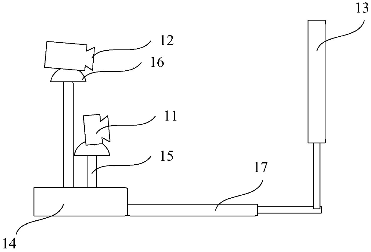
[0043] see figure 1 , the present embodiment provides an analysis system for calibrating cameras and projectors, the analysis system includes a camera 11, a projector 12, a screen 13 for projection, and a processor;

[0044] The processor is respectively connected to the camera and the projector, and the processor sends trigger signals to the camera and the projector respectively;

[0045] The camera includes a camera lens, the projector includes a projection lens, and the shooting direction of the camera lens and the projection direction of the projection lens are both aligned with the screen;

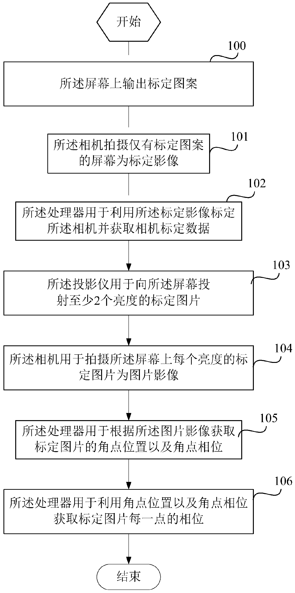
[0046] A calibration pattern is set on the screen;

[0047] The camera shoots a screen with only a calibration pattern as a calibration image;

[0048] The processor is configured to use the calibration image to calibrate the camera, and obtain camera calibration data;

[0049] The projector is used to project at least 2 brightness calibration pictures to the screen;

[0050] The ...

Embodiment 2

[0089] This embodiment is basically the same as Embodiment 1, the only difference is:

[0090] The screen includes a translucent whiteboard and a control chip. The calibration pattern is printed on the front of the translucent whiteboard, and several LED lights are arranged on the back of the translucent whiteboard. The lighting direction of the LED lights is aligned with the translucent whiteboard;

[0091] The control chip is used to control the brightness of the LED lamp;

[0092] The processor is further configured to send a trigger signal to the camera after sending a brightness adjustment signal to the control chip.

Embodiment 3

[0094] This embodiment is basically the same as Embodiment 1, the only difference is:

[0095] The screen is a liquid crystal screen, and the liquid crystal screen displays a preset pattern, the shape of the preset pattern is the same as that of the calibration pattern, and the color of the preset pattern is variable.


PUM


Abstract

The invention discloses an analysis system and method for camera and projector calibration. The analysis system comprises a camera, a projector, a screen for projection and a processor. The processoris connected with the camera and the projector. The processor sends trigger signals to the camera and the projector. The camera shoots a screen only having the calibration pattern as a calibration image; the processor is used for acquiring camera calibration data; the projector is used for projecting a calibration picture; the camera is used for shooting a calibration picture of each brightness onthe screen as a picture image; the processor obtains the angular point position and the angular point phase of the calibration picture according to the picture image; the processor is used for acquiring the phase of each point of the calibration picture. According to the analysis system for camera and projector calibration, the calibration relation between the camera and the projector of the projection grating modeling system and the phase of the image projected by the projector can be obtained, so that the precision of projection grating modeling is higher, and the established model is morefidelity.

Description

technical field [0001] The invention relates to an analysis system and method for calibrating cameras and projectors. Background technique [0002] Three-dimensional reconstruction refers to the establishment of a mathematical model suitable for computer representation and processing of three-dimensional objects. It is the basis for processing, operating and analyzing its properties in a computer environment, and it is also a key technology for establishing a virtual reality that expresses the objective world in a computer. [0003] Three-dimensional reconstruction by grating projection is a three-dimensional reconstruction method. The grating is projected onto the reference plane and the surface of the measured object respectively. Since the reference plane is a horizontal plane, the reference grating projected on it will not be deformed; when the grating is projected onto the measured object When measuring the surface of an object, the grating will have different degrees o...

Claims


Application Information

Patent Timeline
IPC IPC(8): G06T7/80G01B11/25
CPCG06T7/80G01B11/2504
Inventor 袁丹寿孙燕生黄沛杰
Owner 盎维云(深圳)计算有限公司
Why Eureka
Try Eureka