Broadband high-gain slow wave structure

A slow-wave structure, high-gain technology, applied in the field of slow-wave structures, can solve the problem that slow-wave structures cannot meet the needs of broadband and high gain, and achieve the effect of shortening size and size

Active Publication Date: 2019-07-26
UNIV OF ELECTRONICS SCI & TECH OF CHINA
View PDF4 Cites 6 Cited by
  • Summary
  • Abstract
  • Description
  • Claims
  • Application Information

AI Technical Summary

Problems solved by technology

[0006] As the frequency increases to the terahertz band, the existing...

Method used


Image

  • Broadband high-gain slow wave structure
  • Broadband high-gain slow wave structure
  • Broadband high-gain slow wave structure

Examples


Embodiment Construction

[0020] Specific embodiments of the present invention will be described below in conjunction with the accompanying drawings, so that those skilled in the art can better understand the present invention. It should be noted that in the following description, when detailed descriptions of known functions and designs may dilute the main content of the present invention, these descriptions will be omitted here.

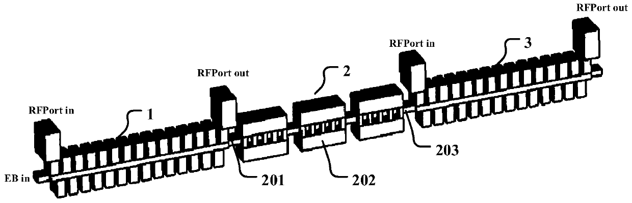
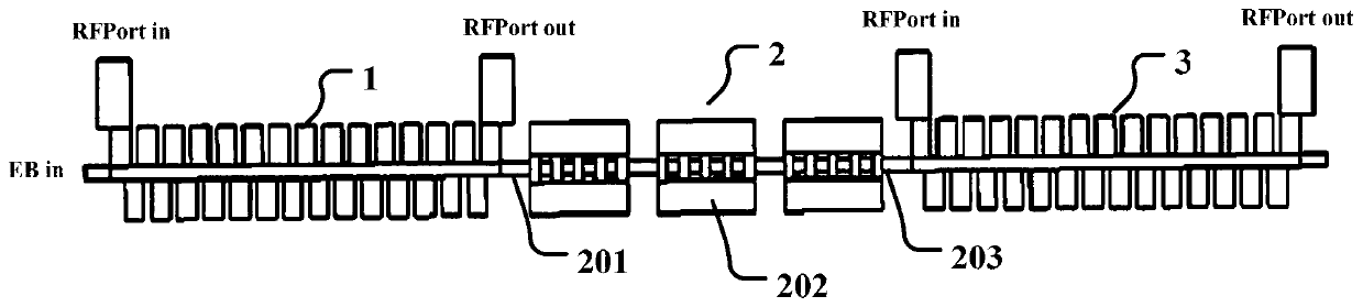
[0021] figure 1 It is a structural schematic diagram of a specific embodiment of the wide-band high-gain slow-wave structure of the present invention.

[0022] In this example, if figure 1 As shown, the wide-band high-gain slow-wave structure includes a first traveling-wave slow-wave structure 1 , a standing-wave slow-wave structure 2 and a second traveling-wave slow-wave structure 3 .

[0023] Input the electromagnetic signal from the electromagnetic signal input port RFPort in at the beginning of the first traveling wave type slow wave structure 1, and pre-modulate with...


PUM


Abstract

The invention discloses a broadband high-gain slow wave structure. The broadband high-gain slow wave structure comprises a first traveling wave type slow wave structure, a second traveling wave type slow wave structure and a standing wave type slow wave structure between the first traveling wave type slow wave structure and the second traveling wave type slow wave structure, a traditional standingwave type slow wave structure is combined with a traveling slow wave structure so as to create a novel interaction slow wave structure. In the first traveling wave type slow wave structure, premodulation is carried out on an input electromagnetic signal, an electron beam is carried with information in the electromagnetic signal, then the electron beam is fed into the standing wave type slow wavestructure for further modulation, the carried information is further amplified, and finally the electron beam is used for stimulating the electromagnetic signal in the second traveling wave type slowwave structure and further carrying out beam-wave interaction, so that the amplified electromagnetic signal is output by the second traveling wave slow wave structure. The standing wave type slow wavestructure is introduced in a traditional wave slow wave structure, and the size of an original slow wave structure interaction circuit part is shortened effectively, so that the purposes of the invention such as broad band and high gain are realized by using the advantages that the size of a standing wave type slow wave structure interaction circuit is short, the gain is high and the frequency band of the traveling wave type slow wave structure is wide.

Description

technical field [0001] The invention belongs to the technical field of microwave electric vacuum devices, and more specifically relates to a wide-band high-gain slow-wave structure. Background technique [0002] Traveling wave tubes and klystrons, as microwave power amplifier devices with a wide range of applications, have a very rich variety of products in both military and civilian fields. [0003] Due to its irreplaceable broadband characteristics, traveling wave tubes have become widely used microwave devices. As a high-power, high-gain and high-efficiency standing wave field vacuum electronic device, klystron has been extensively studied in scientific research, national defense construction and industrial fields. [0004] At present, the extended interaction klystron, which is widely used in klystrons, has the characteristics of high characteristic impedance and high gain in a short distance compared with other microwave devices due to the use of multi-gap resonant cav...

Claims


Application Information

Patent Timeline
IPC IPC(8): H01J23/24
CPCH01J23/24
Inventor 宫玉彬师凝洁张长青王战亮潘依林邵伟陈亚鸣许多
Owner UNIV OF ELECTRONICS SCI & TECH OF CHINA
Why Eureka
Try Eureka