Cable pay-off device for power construction

A technology of pay-off device and electric construction, applied in cable laying equipment and other directions, can solve the problems of aggravating the difficulty of pulling cables, low cable laying efficiency, waste of manpower and material resources, etc., and achieve the effect of enhancing convenience, reducing labor intensity and improving efficiency.

Active Publication Date: 2019-07-26
RES INST OF ECONOMICS & TECH STATE GRID SHANDONG ELECTRIC POWER +1
View PDF9 Cites 22 Cited by
  • Summary
  • Abstract
  • Description
  • Claims
  • Application Information

AI Technical Summary

Problems solved by technology

[0003] In the process of power installation, cables are often difficult to lay, and because the cables are very heavy, several people need to drag them when they are laid out, which consumes a lot of manpower and material resources, especially the resistance of the ground exacerbates the difficulty of pulling cables; Multiple cables need to be erected. The traditional cable laying method is generally to repeat the previous laying process after laying one cable, resulting in a large amount of labor for workers and low efficiency of cable laying.

Method used


Image

  • Cable pay-off device for power construction
  • Cable pay-off device for power construction
  • Cable pay-off device for power construction

Examples


Embodiment Construction

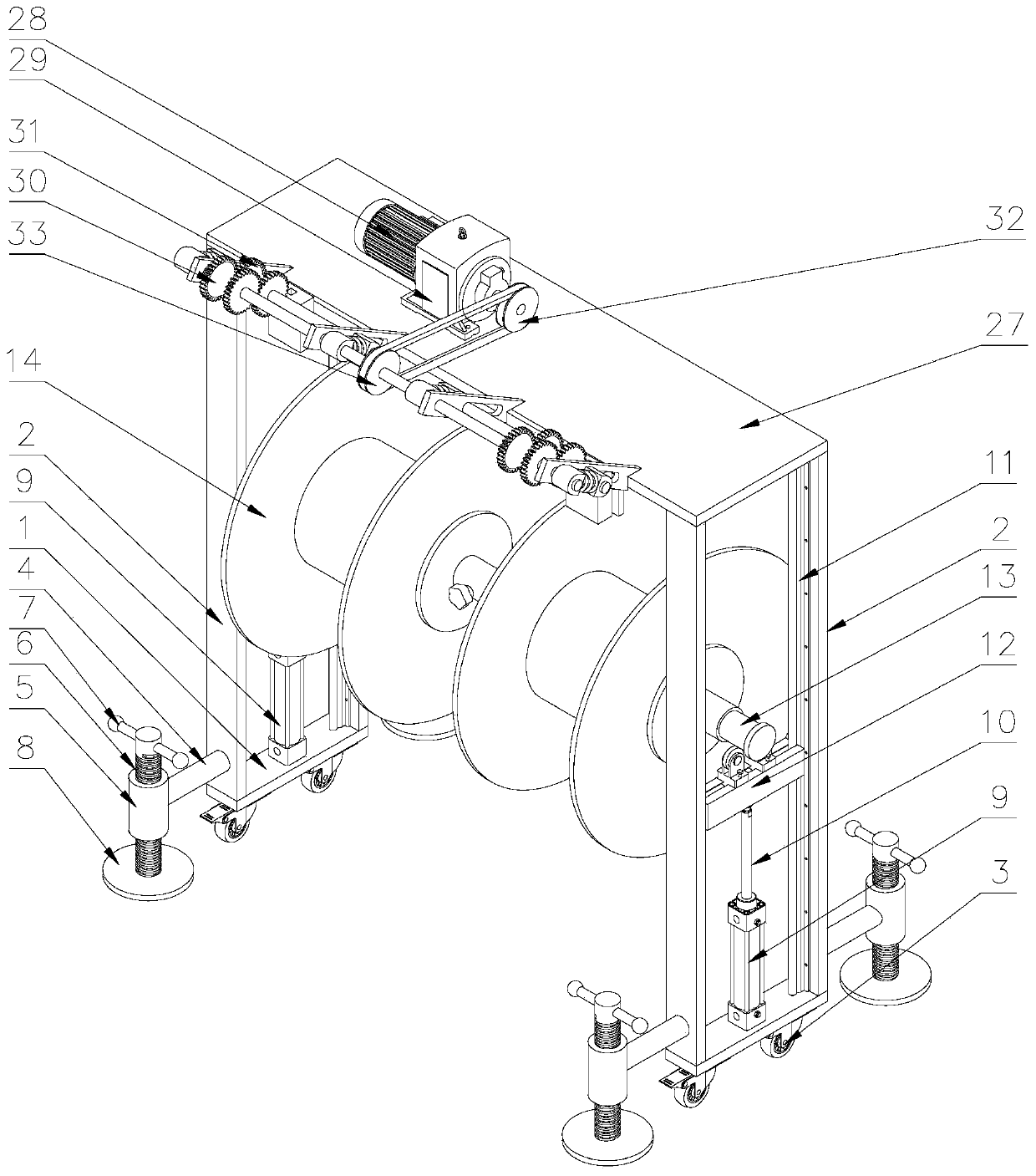
[0038] Attached below Figure 1-9 , clearly and completely describe the technical solutions in the embodiments of the present invention, obviously, the described embodiments are only some of the embodiments of the present invention, not all of them. Based on the embodiments of the present invention, all other embodiments obtained by persons of ordinary skill in the art without making creative efforts belong to the protection scope of the present invention.

[0039] In describing the present invention, it should be understood that the terms "longitudinal", "transverse", "upper", "lower", "front", "rear", "left", "right", "vertical", The orientations or positional relationships indicated by "horizontal", "top", "bottom", "inner", "outer", etc. are based on the orientations or positional relationships shown in the drawings, and are only for the convenience of describing the present invention, rather than indicating or It should not be construed as limiting the invention by imply...


PUM


Abstract

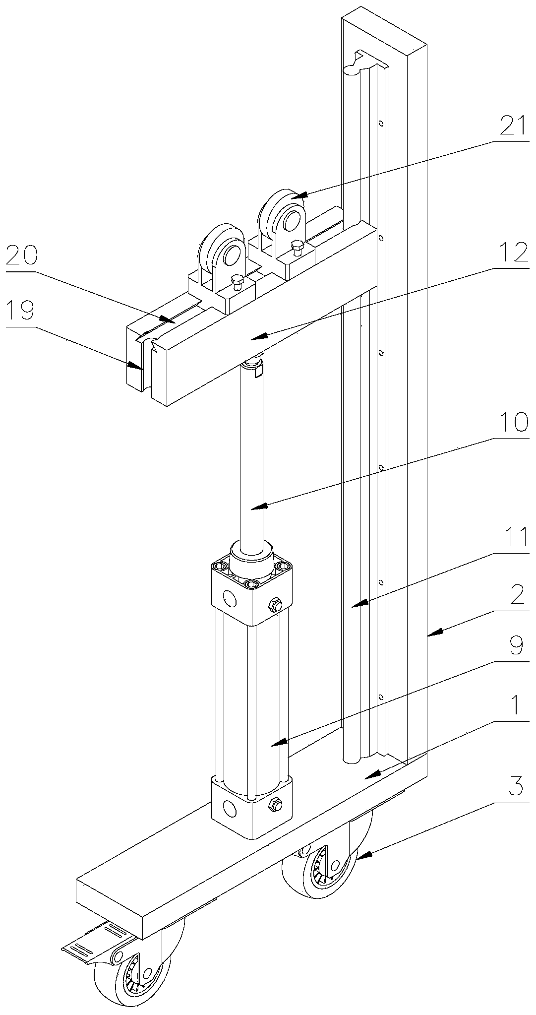
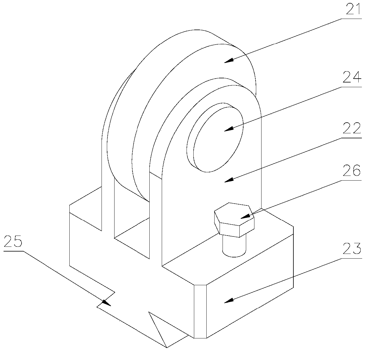
The invention discloses a cable pay-off device for power construction. Vertical posts are arranged at two ends of a bottom plate, a guide rail is arranged at one side of each vertical post, an air cylinder is fixedly arranged on the bottom plate, a first sliding block is arranged at an upper end of a piston rod of the air cylinder, upper ends of the vertical posts at two sides are connected by a top plate, two ends of a second connection rod are placed on the first sliding block, a plurality of cable discs are arranged on the second connection rod, a plurality of second supports are arranged at one side f the top plate, a first rotation shaft is arranged on the second supports, a plurality of winding wheels are movably arranged on the first rotation shaft, the numbers of the first windingwheels are equal to the numbers of the cable discs, and the first winding wheel slides among the second supports along an axial direction of the first rotation shaft. The cable disc is jacked up by the air cylinder, the cable disc is prevented from being contacted with ground, so that the friction between the cable disc and the ground is prevented, and the cable pay-off difficulty is reduced; andmoreover, multiple groups of cable discs are arranged on the second connection rod and are used for unwinding, the labor intensity of a worker is reduced, and the cable laying efficiency is greatly improved.

Description

technical field [0001] The invention belongs to the technical field of electric power construction, in particular to a cable pay-off device for electric power construction. Background technique [0002] In the production process of wires and cables, in order to facilitate production and transportation, the cables are usually wound on the cable reel, and a pay-off machine is required for subsequent cable laying; cable laying can be divided into overhead, There are several laying methods such as underground (pipeline and direct burial), underwater, wall and tunnel; reasonable selection of cable laying method is very important to ensure the transmission quality, reliability and construction maintenance of the line. [0003] In the process of power installation, cables are often difficult to lay, and because the cables are very heavy, several people need to drag them when they are laid out, which consumes a lot of manpower and material resources, especially the resistance of the...

Claims


Application Information

Patent Timeline
Patent Type & Authority Applications(China)
IPC IPC(8): H02G1/06
CPCH02G1/06
Inventor 朱毅夏佩源张浩曾军孙东磊亓超黄义波赵鹏飞苏静华徐亚玮
Owner RES INST OF ECONOMICS & TECH STATE GRID SHANDONG ELECTRIC POWER
Why Eureka
Try Eureka