
Out-sync swaging drawing forming mould and forming process thereof

A molding die and molding process technology, which is applied in the field of non-synchronous pressing and drawing molding dies and its molding process, can solve problems that affect the mold manufacturing cycle, complex product shapes, and complex shape changes, and achieve insufficient wrinkling and cracking Problems, reasonable design of forming process, and the effect of improving drawing quality

Pending Publication Date: 2019-07-30
FUZHEN TECH RES ANHUI
View PDF6 Cites 6 Cited by
  • Summary
  • Abstract
  • Description
  • Claims
  • Application Information

AI Technical Summary

Problems solved by technology

However, it is not ideal for the application of automotive inner panels with special product shapes. Typical panel back door inner panels, especially aluminum alloy back door inner panels with small curvature and complex drawing. These products are characterized by flat flange areas and drawn The drawing depth is shallow and the product shape is complicated. If such parts are drawn and formed according to the conventional process, there will be insufficient forming of the flange area, complex shape changes and sharp position cracking, accompanied by severe wrinkles.
These problems cannot be completely solved through debugging in actual mold manufacturing, which will not only reduce the quality of automobile panel products, but also affect the mold manufacturing cycle
Secondary deep drawing is one of the means to solve this problem, but adding a drawing process means adding a set of stamping dies and increasing development costs

Method used


Image

  • Out-sync swaging drawing forming mould and forming process thereof
  • Out-sync swaging drawing forming mould and forming process thereof

Examples


Embodiment Construction

[0033] The specific implementation manner of the present invention will be described in further detail below by describing the embodiments with reference to the accompanying drawings.

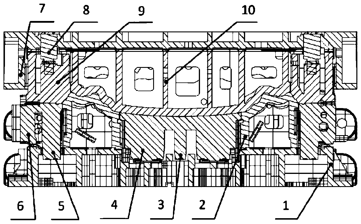
[0034] The asynchronous pressing and drawing forming die includes an upper die body, a lower die base, a punch and a die, the die is set on the lower part of the upper die body, the punch is set on the upper part of the lower die base, and the punch is fixed on the lower die On the seat, the outer side of the punch is provided with a movable lower blank holder, and the center of the punch is provided with a movable support core, the punch and the support core are slidably fitted, and the die is fixed on the upper die body to form a fixed convex Die, the outer side of the die is provided with a movable upper binder ring, the upper binder ring and the lower binder ring are set up and down oppositely, and the lower surface of the die is set opposite to the upper surface of the punch and the support...


PUM


Abstract

The invention discloses an out-sync swaging drawing forming mould which comprises an upper die body, a lower die base, a male die and a female die. The female die is arranged on the lower part of theupper die body; the male die is arranged on the upper part of the lower die base and is fixedly arranged on the lower die base; a movable lower binder ring is arranged on the outer side of the male die; a movable support core is arranged in the center of the male die; the male die and the support core are in sliding fit; the female die is fixedly arranged on the upper die body so as to form a fixed male die; a movable upper binder ring is arranged on the outer wall of the female die and is arranged opposite to the lower binder ring up and down; and the lower surface of the female die and the upper surfaces of the male die and the support cores are arranged oppositely so as to be used for plate forming. A small-curvature back door inner plate out-sync binder ring drawing forming mould realizes multi-time drawing forming in one process, so that the problem that a small-curvature complex inner covering piece aluminum alloy workpiece is insufficient in drawing forming so as to be wrinkledand cracked is solved, the drawing quality is improved, and the cost is reduced since only one-step stamping forming is needed.

Description

technical field [0001] The invention relates to the technical field of drawing forming, in particular to a non-synchronous pressing drawing forming mold and a forming process thereof. Background technique [0002] Existing drawing die structure such as figure 2 As shown, it mainly consists of three major parts, the die, the blank holder and the punch. The drawing forming process is as follows: the die is lowered with the slider on the press at the beginning of stamping, and the die contacts the plate and the blank holder and moves with the press. Further down, at the same time, the lower air point of the press withstands the joint action of the mold ejector rod and the blank holder, the plate contacts the punch, and the die is under the action of the press, and the die presses the plate and the blank holder down to the dead point, so far the die, blankholder and punch are closed with the press to the dead point to complete the drawing of the plate; with the return stroke of...

Claims


Application Information

Patent Timeline
Patent Type & Authority Applications(China)
IPC IPC(8): B21D25/02B21D37/10
CPCB21D25/02B21D37/10
Inventor 汤金所张威刘庆华袁根成
Owner FUZHEN TECH RES ANHUI
Learn More