
Combined impeller and compressor of gas turbine engine

An impeller and hub technology, applied in liquid fuel engines, machines/engines, mechanical equipment, etc., can solve problems such as airflow mixing and blade resonance, and achieve the effects of reducing operating costs, increasing rigidity, and improving vibration performance.

Inactive Publication Date: 2019-07-30
AECC HUNAN AVIATION POWERPLANT RES INST
View PDF9 Cites 1 Cited by
  • Summary
  • Abstract
  • Description
  • Claims
  • Application Information

AI Technical Summary

Problems solved by technology

[0004] The invention provides a combined impeller to solve the technical problems that the impeller part of the compressor in the existing gas turbine engine is prone to produce airflow spanwise mixing and blade resonance

Method used


Image

  • Combined impeller and compressor of gas turbine engine
  • Combined impeller and compressor of gas turbine engine
  • Combined impeller and compressor of gas turbine engine

Examples


Embodiment Construction

[0030] The embodiments of the present invention will be described in detail below with reference to the accompanying drawings, but the present invention can be implemented in various ways defined and covered below.

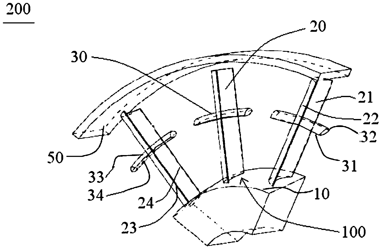
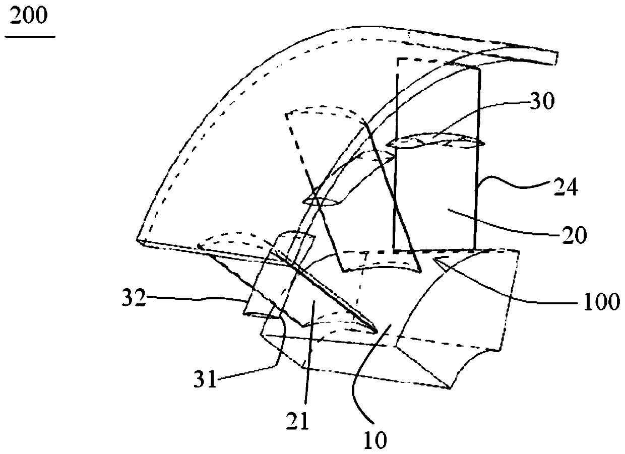
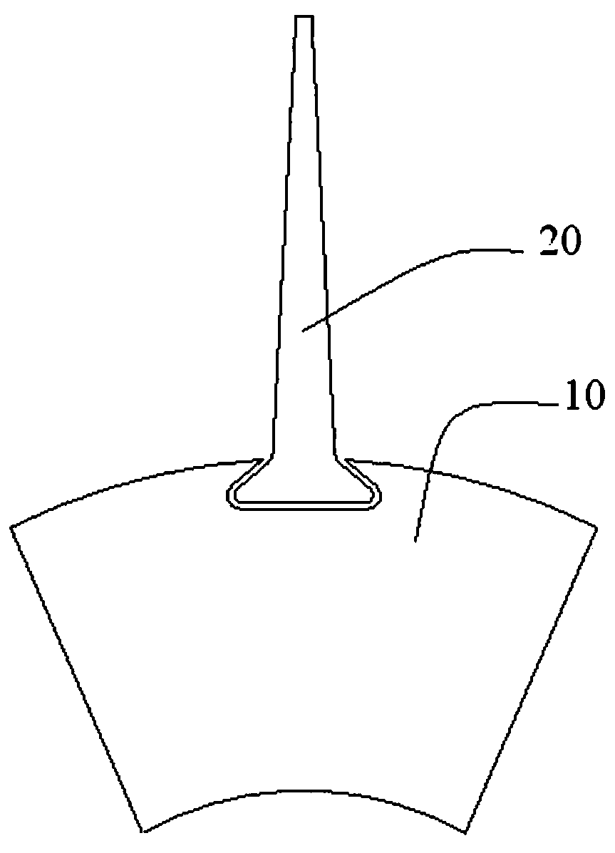
[0031] figure 1 is the front view of the combined impeller of the preferred embodiment of the present invention; figure 2 is the rear view of the combined impeller of the preferred embodiment of the present invention; image 3 It is a structural schematic diagram of the connection between the hub and the rotor blade in the preferred embodiment of the present invention; Figure 4 It is a structural schematic diagram of the connection between the rotor blade and the winglet in the preferred embodiment of the present invention; Figure 5 It is a structural schematic diagram of the connection between the rotor blade and the winglet according to the second embodiment of the present invention; Figure 6 is a schematic diagram of the installation position of the wing...


PUM


Abstract

The invention discloses a combined impeller. The combined impeller comprises a hub, a plurality of rotor blades distributed along the radial direction of the hub, and winglets distributed along the circumferential direction of the combined impeller, wherein the plurality of rotor blades are arranged at intervals along the circumferential direction of the hub; each rotor blade comprise a pressure surface and a suction surface; and the winglets respectively penetrate through the pressure surface and the suction surface along the circumferential direction of the combined impeller, and used for inhibiting airflow spreading mixing in airflow passages between adjacent rotor blades and inhibiting resonance generated among the rotor blades. According to the technical scheme, the winglets distributed along the circumferential direction of the combined impeller are arranged, so that the rigidity of the rotor blades is increased, the effect of a damper is achieved, the vibration energy caused byunsteady aerodynamic force and centrifugal force is absorbed, the vibration of the rotor blades is restrained, and the vibration performance of the rotor blades is improved; and as the winglets penetrate through the pressure surface and the suction surface respectively, radial separation is restrained by adopting a physical blocking method, and airflow separation caused by spreading mixing is restrained.

Description

technical field [0001] The present invention relates to the technical field of turbomachinery, in particular to a combined impeller. The invention also relates to a compressor for a gas turbine engine. Background technique [0002] At present, the compressor of a gas turbine engine is mainly used to continuously suck in air from the atmosphere and compress it. In order to continuously improve the performance of the fan or compressor, the number of rotor blades of the fan or compressor becomes less and less, which makes the air flow more prone to spanwise separation in the rotor blade channel of the compressor; at the same time, in order to improve the fan or compressor The aerodynamic performance of the rotor blade becomes thinner and thinner, which makes the vibration characteristics of the rotor blade worse. [0003] Due to the centrifugal force in the compressor passage (the airflow passage between two adjacent rotor blades) on the existing compressor, there is a pressu...

Claims


Application Information

Patent Timeline
Patent Type & Authority Applications(China)
IPC IPC(8): F04D29/32F04D29/38F04D29/66
CPCF04D29/324F04D29/668
Inventor 吴仕钰银越千彭文雯金海良
Owner AECC HUNAN AVIATION POWERPLANT RES INST
Learn More