
Reactive power compensation control device and capacitor switching method

A compensation control, capacitor switching technology, applied in reactive power compensation, reactive power adjustment/elimination/compensation, measurement devices, etc., which can solve the problems of limited temperature measurement points of capacitors, large cables, and inability to detect capacitor capacitance values. , to avoid long-term overload operation, avoid capacitor resonance, and reduce the effect of installing temperature controllers

Pending Publication Date: 2019-07-30
浙江朗松智能电力设备有限公司
View PDF0 Cites 4 Cited by
  • Summary
  • Abstract
  • Description
  • Claims
  • Application Information

AI Technical Summary

Problems solved by technology

Capacitors are very sensitive to temperature. When the temperature of the capacitor is too high, it is easy to cause thermal breakdown of the capacitor, and overvoltage and overcurrent further accelerate the destruction of the insulation performance of the capacitor.
Some capacitors are used in a harsh environment, coupled with the hot and humid indoor air in summer, the heat generated by the normal operation of the capacitor cannot be dissipated in a timely and effective manner, which destroys the dynamic balance of heat dissipation on the surface of the capacitor shell, resulting in a rapid rise in the temperature of the capacitor during operation, thus accelerating the electrical The aging speed of the insulating medium of the equipment. The insulating medium of the capacitor will be operated at high field strength and high temperature for a long time, resulting in an increase in dielectric loss and dielectric breakdown, which will cause the temperature of the capacitor to rise and the capacitance to decay.
[0003] After the capacitor is put into operation, the capacitance value continues to decay, and the internal temperature of the capacitor may be too high
However, the existing low-voltage reactive power compensation controller only has capacitor switching, and cannot detect the temperature of each control output capacitor, and cannot detect the capacitance of the capacitor
Capacitor capacitance measurement generally relies on measuring the capacitance of capacitors one by one with special instruments on a regular basis, which is very time-consuming and laborious
The method of capacitor overheating protection is to use an additional temperature controller to measure the temperature of the capacitor shell. The output circuit of the temperature controller is connected in series with the control circuit of the capacitor switching switch, and the output circuit of the temperature controller is less, so a large number of cables are required. also limited

Method used


Image

  • Reactive power compensation control device and capacitor switching method
  • Reactive power compensation control device and capacitor switching method
  • Reactive power compensation control device and capacitor switching method

Examples


Embodiment 1

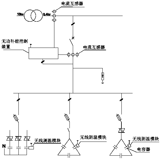
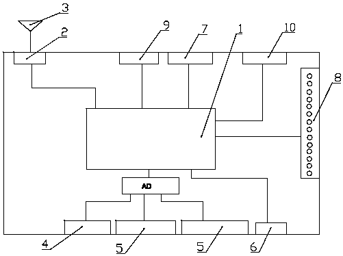
[0019] Such as figure 2 As shown, a reactive power compensation control device described in this embodiment includes a radio frequency module 2, an antenna 3, an MCU controller 1, a three-phase voltage acquisition circuit 4, two sets of three-phase current acquisition circuits 5, and a capacitor switching circuit 9. Alarm output circuit 8, temperature control circuit 10, wherein MCU controller 1 is respectively connected with three-phase voltage acquisition circuit 4, three-phase current acquisition circuit 5, capacitor switching circuit 9, alarm output circuit 8, and temperature control circuit 10 , the three-phase voltage acquisition circuit 4 is directly connected with the grid three-phase power supply for detecting the three-phase voltage of the grid, wherein a set of three-phase current acquisition circuits 5 is provided with a current transformer on the grid power supply side for detecting the grid power supply side total current, another set of three-phase current acqu...


PUM


Abstract

The invention relates to the field of power equipment, in particular to a reactive power compensation control device comprising a radio frequency module, an antenna, an MCU controller, a three-phase voltage collecting circuit, two sets of three-phase current collecting circuits, a capacitor switching circuit, an alarm output circuit and a temperature control circuit, wherein the MCU controller isrespectively connected to the three-phase voltage collecting circuit, the three-phase current collecting circuits, the capacitor switching circuit, the alarm output circuit and the temperature controlcircuit. A capacitor switching method sets the capacity of the capacitor and an over-temperature protection value of the capacitor. The MCU controller controls the corresponding capacitor to be put into operation, and cuts off the capacitor loop and outputs an alarm when the temperature of the capacitor exceeds the set upper limit. The reactive power compensation controller and the capacitor switching method obtained by the invention have the function of wireless temperature measurement and capacitance detection of the capacitor.

Description

technical field [0001] The invention relates to the field of electric equipment, in particular to a reactive power compensation control device and a capacitor switching method. Background technique [0002] At present, the scale of my country's power system is expanding day by day, and the reactive power required for the work of various electrical equipment is also increasing. Capacitors, as the core components of reactive power compensation devices, can improve power factor, improve voltage quality, and reduce line It is an important guarantee for the safe operation of the power system to reduce losses, increase the output power of the system or transformer, reduce voltage fluctuations, and achieve the purpose of stable system operation. However, due to the complex operating conditions of the power grid, the operation of impact equipment, nonlinear equipment and other equipment causes voltage fluctuations, flicker, and harmonics. During the long-term operation of the capaci...

Claims


Application Information

Patent Timeline
IPC IPC(8): H02J3/18G01D21/02
CPCH02J3/1821G01D21/02Y02E40/30
Inventor 陈龙李磊李大鹏
Owner 浙江朗松智能电力设备有限公司
Learn More