
A vehicle flywheel battery with anti-radial gyro effect

A flywheel battery, gyroscopic effect technology, applied in motors, electric components, electric vehicles, etc., can solve the problems of serious radial gyroscopic effect, large space occupation rate, high price, etc., to suppress gyroscopic effect and large radial bearing capacity. , the effect of large bearing capacity

Active Publication Date: 2020-11-03
JIANGSU UNIV
View PDF4 Cites 0 Cited by
  • Summary
  • Abstract
  • Description
  • Claims
  • Application Information

AI Technical Summary

Problems solved by technology

[0004] The purpose of the present invention is to overcome the problems of severe radial gyro effect, large space occupation rate, high price and high energy consumption in the existing vehicle-mounted flywheel energy storage device, and propose a method for radial gyro effect on the basis of satisfying energy storage. High-stability, high-integration, low-energy-consumption vehicle flywheel battery for severe road conditions with gyro effect

Method used


Image

  • A vehicle flywheel battery with anti-radial gyro effect
  • A vehicle flywheel battery with anti-radial gyro effect
  • A vehicle flywheel battery with anti-radial gyro effect

Examples


Embodiment Construction

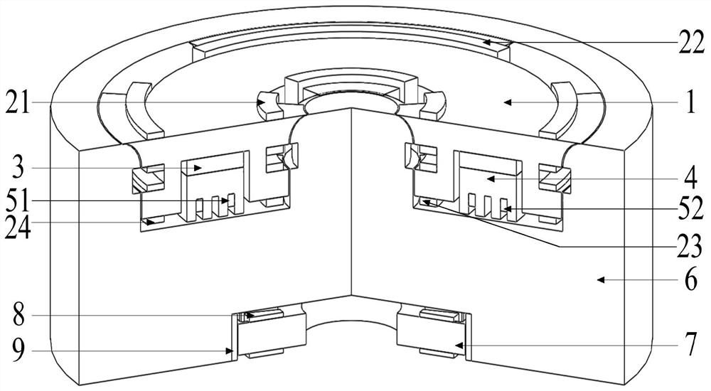
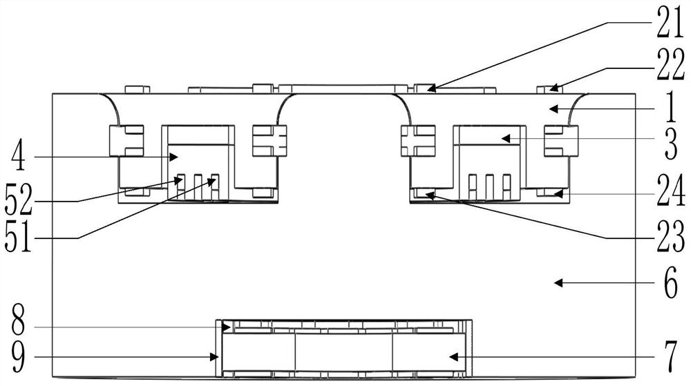
[0039] see figure 1 and figure 2 As shown, the present invention has a five-degree-of-freedom magnetic bearing coaxially distributed, a flywheel rotor 6 and an outer rotor motor. Among them, the five-degree-of-freedom magnetic bearing includes a radial stator 1 , an axial stator 4 , and a bearing permanent magnet 3 , and the bearing permanent magnet 3 and the axial stator 4 are installed inside the radial stator 1 . The outer rotor motor includes a motor stator 7, a motor coil 8, and a motor permanent magnet 9. The five-degree-of-freedom magnetic bearing is coaxially embedded in the upper section of the flywheel rotor 6 , and the outer rotor motor is coaxially embedded in the lower section of the flywheel rotor 6 . The five-degree-of-freedom magnetic bearing, the flywheel rotor 6 and the outer rotor motor are fixed in one body.

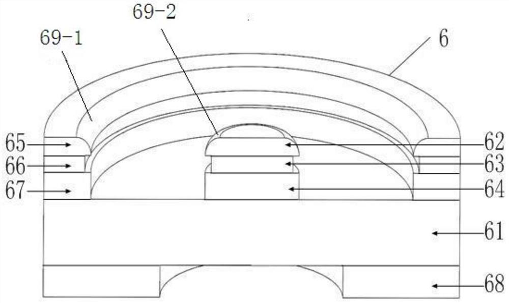
[0040] see image 3 Shown is a perspective view of the structure of the flywheel rotor 6 . The flywheel rotor 6 is a cylindrical structure as a...


PUM


Abstract

The invention discloses a radial gyrostatic effect-resisting vehicle flywheel battery. The vehicle flywheel battery comprises a flywheel rotor, wherein the middle section of the flywheel rotor is a flywheel rotor main cylinder; a lower-end ring receiving pole, a middle ring and an upper-end ring receiving pole which are concentrically sequentially fixedly connected at the outer edge of the upper surface of the flywheel rotor main cylinder from bottom to top and a lower-end disk receiving pole, a middle disk and an upper-end disk receiving pole which are concentrically sequentially fixedly connected in the middle of the upper surface of the flywheel rotor main cylinder from bottom to top are arranged at the upper section of the flywheel rotor; the upper edge of the inner wall of the upper-end ring receiving pole is a quarter of the inner-wall arc surface which is protruded inward; the upper edge of the outer wall of the upper-end disk receiving pole is a quarter of the outer-wall arc surface which is protruded outward; a radial stator is arranged in an upper-section groove of the flywheel rotor; the lower section of the flywheel rotor is a flywheel rotor lower torus; a lower-sectioncylindrical groove is formed between the flywheel rotor lower torus and the flywheel rotor main cylinder; and an external rotor motor is arranged in the lower-section cylindrical groove. The vehicleflywheel battery has the beneficial effect that the gyrostatic effect in the radial direction is suppressed.

Description

technical field [0001] The invention relates to a vehicle-mounted flywheel battery structure for an electric vehicle, which is suitable for the electric vehicle that often runs on road conditions with serious radial gyro effects such as roads around mountains and many left and right curves. Background technique [0002] Flywheel battery is a kind of mechanical energy storage battery. It has the advantages of high charging efficiency, high power, small mass, no pollution and long life. It is an ideal power battery for electric vehicles. However, when the vehicle-mounted flywheel battery is applied to road conditions with severe radial gyro effect, such as roads around mountains, left and right curves, etc., there are still many problems restricting its large-scale application, mainly manifested in serious radial gyro effect, large space occupation rate and Problems such as large energy consumption. [0003] At present, the topology of flywheel energy storage devices at home ...

Claims


Application Information

Patent Timeline
Patent Type & Authority Patents(China)
IPC IPC(8): H02K7/02H02K7/09
CPCH02K7/025H02K7/09Y02E60/16Y02T10/64
Inventor 张维煜王健萍朱鹏飞秦英李凯张林东张松朱熀秋
Owner JIANGSU UNIV
Learn More