Direct current motor braking device and method with controllable constant current and falling speed

A technology of DC motors and braking devices, which is applied in the direction of the reduction device of DC motors, electric motor/converter plugs, etc., can solve the problems that cannot be changed, and it is difficult to satisfy the variable speed of heavy objects, so as to ensure stability and meet industrial reliability. Sexual requirements, the effect of strong versatility

Active Publication Date: 2019-07-30
LIAONING UNIVERSITY OF PETROLEUM AND CHEMICAL TECHNOLOGY
View PDF8 Cites 2 Cited by
  • Summary
  • Abstract
  • Description
  • Claims
  • Application Information

AI Technical Summary

Problems solved by technology

In addition, for potential energy loads such as lowering heavy objects such as cranes, once the hardware structure of the above-mentioned three existing electric brake circuits is determined, the stable lowering speed of the load will be determined accordingly and cannot be changed. It is difficult to meet the requirements of heavy objects in certain working conditions. decentralization requirements

Method used


Image

  • Direct current motor braking device and method with controllable constant current and falling speed
  • Direct current motor braking device and method with controllable constant current and falling speed
  • Direct current motor braking device and method with controllable constant current and falling speed

Examples


Embodiment Construction

[0046] The technical solution and system working principle of the present invention will be described in detail below in conjunction with the accompanying drawings. The hardware structure of the DC motor braking device with constant current and controllable falling speed is as follows: figure 1 As shown, it mainly includes four parts: the current closed-loop adjustment unit, the speed closed-loop adjustment unit, the voltage-controlled rheostat unit with the power MOS tube as the core, and the control unit.

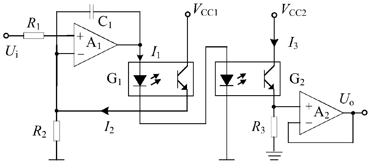
[0047] Among them, the current closed-loop adjustment unit includes the current sampling resistor R s , an inverter, a linear optical isolation amplifier, a current PI regulator 1 and a D / A converter. The D / A converter is used to convert the braking current value set by the controller into the corresponding analog voltage and serve as the given value of the current regulator (PI regulator 1). This unit is used for motor parking constant current braking. The current reg...


PUM


Abstract

The invention discloses a direct current motor braking device with controllable constant current and falling speed, and relates to the technical field of motor application. The power field effect transistor replaces a conventional dynamic braking resistor, and the equivalent resistance between the drain and the source of the power field effect transistor is adjusted in real time in a voltage control mode to realize the constant-current parking braking of the motor, so that the braking time is shortened to be less than 68 percent of that of the conventional dynamic braking mode. Under the condition of not changing hardware, the intelligent continuous control of the motor braking current and the potential energy load falling speed is realized by adopting a current and rotating speed two-stage closed-loop control technology and a digital signal processor. In order to increase the reliability of the control system, an optical isolator with double optical couplers as cores is designed and used for reliably isolating analog signals between a control stage and a power stage. The invention can realize the braking at the highest speed in the motor dragging process and the continuous regulation control of the falling speed of the potential energy load.

Description

technical field [0001] The invention relates to the technical field of motor driving and control, in particular to a DC motor braking device and method with constant current and controllable falling speed. Background technique [0002] In industrial and agricultural production, a large number of large and medium-sized motors are used as prime movers to drive various production machinery and equipment. In the field of automation, various small control motors are widely used as detection, amplification and actuators. As an important branch of the motor field, DC motors have been widely used in modern life due to their good starting, speed regulation characteristics and large torque. [0003] DC motors often need braking during operation. For resistive loads, the purpose of braking is to reduce or stop the speed of the drag system; for working mechanisms with potential energy loads, braking can obtain a stable load falling speed. [0004] Motor braking methods can be generall...

Claims


Application Information

Patent Timeline
Patent Type & Authority Applications(China)
IPC IPC(8): H02P3/12
CPCH02P3/12
Inventor 白海城
Owner LIAONING UNIVERSITY OF PETROLEUM AND CHEMICAL TECHNOLOGY
Why Eureka
Try Eureka