
Grain-oriented electrical steel sheet and method for manufacturing same

A technology of electromagnetic steel sheet and manufacturing method, applied in the direction of inductor/transformer/magnet manufacturing, manufacturing tools, circuits, etc., can solve the problems of deterioration, inability to maximize the use of the good characteristics of the product board, and high cost

Active Publication Date: 2019-07-30
JFE STEEL CORP
View PDF22 Cites 0 Cited by
  • Summary
  • Abstract
  • Description
  • Claims
  • Application Information

AI Technical Summary

Problems solved by technology

However, due to the use of Ar, H 2 will make the cost higher, so in many cases use N 2 Gas, containing CO or CO 2 DX gas
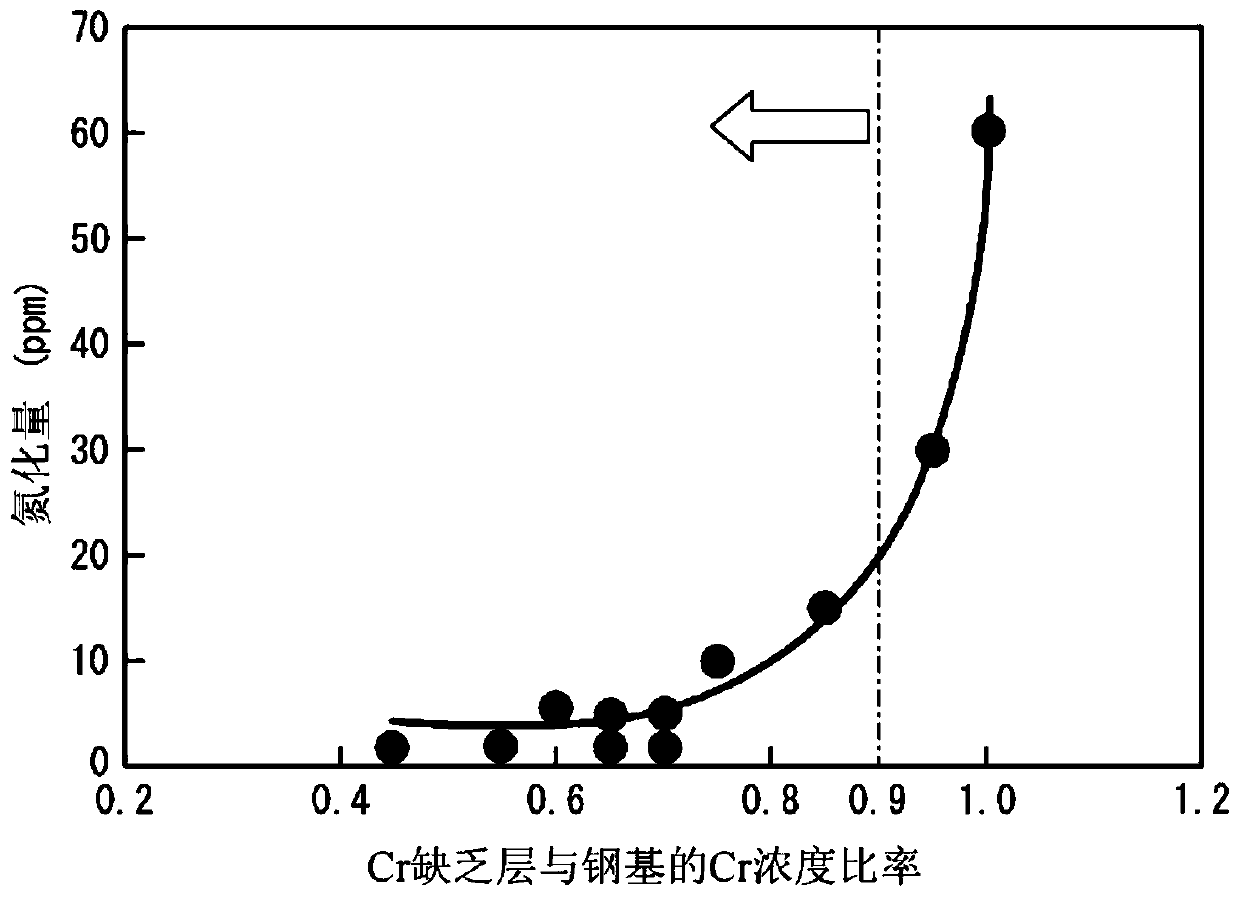
Use N 2 , DX gas, if the annealing temperature is too high, nitriding, oxidation, carburization will occur, and the magnetic properties will be deteriorated. Therefore, there is a substantial upper limit to the annealing temperature. The problem of maximizing the good features of the product board

Method used


Image

  • Grain-oriented electrical steel sheet and method for manufacturing same
  • Grain-oriented electrical steel sheet and method for manufacturing same
  • Grain-oriented electrical steel sheet and method for manufacturing same

Examples


Embodiment 1

[0152] Continuous casting was used to manufacture a steel slab whose composition contained the ingredients shown in Table 7 and the remainder was substantially Fe. After heating to 1420°C, it was hot-rolled to form a hot-rolled sheet with a thickness of 1.8mm, and then heated at 1000°C. Annealing of the hot-rolled sheet was performed for 100 seconds. Then, use cold rolling to make the middle plate thickness: 0.45mm, according to the oxidation degree PH 2 O / PH 2 =0.40, temperature: 1000° C., and time: 70 seconds were used for intermediate annealing. Thereafter, the inner layer scale (subscale) on the surface was removed by pickling with hydrochloric acid, and cold rolling was performed again to obtain a cold-rolled sheet having a thickness of 0.23 mm.

[0153] Next, perform decarburization annealing at a soaking temperature of 830°C for 300 seconds, then apply an annealing separator mainly composed of MgO, and perform secondary recrystallization at 1200°C for 30 hours. Final...

Embodiment 2

[0164] Continuous casting was used to manufacture a slab whose composition contained the ingredients shown in Table 9 and the remainder was substantially Fe. After heating to 1400° C., it was hot-rolled to produce a hot-rolled sheet with a thickness of 2.6 mm, and then rolled at 950 °C for 10 seconds of hot-rolled sheet annealing. Then, use cold rolling to make the middle plate thickness: 0.80mm, according to the oxidation degree PH 2 O / PH 2 =0.35, temperature: 1070° C., and time: 200 seconds were used for intermediate annealing. Thereafter, the inner layer scale on the surface was removed by pickling with hydrochloric acid, and cold rolling was performed again to obtain a cold-rolled sheet having a thickness of 0.20 mm.

[0165] Next, perform decarburization annealing at a soaking temperature of 860°C for 30 seconds, then apply an annealing separator mainly composed of MgO, and perform secondary recrystallization of magnesium at 1150°C for 10 hours. Final finish annealing ...


PUM


Abstract

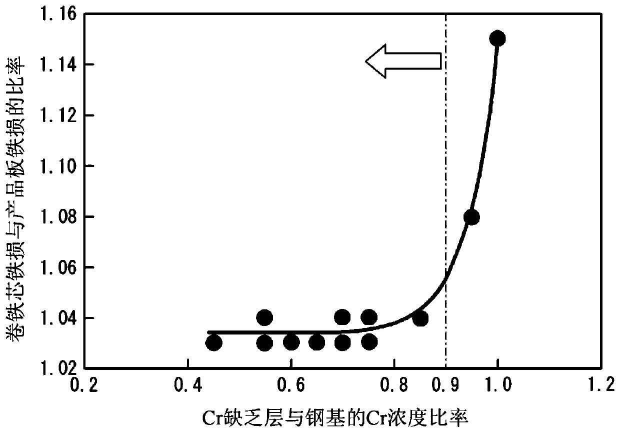
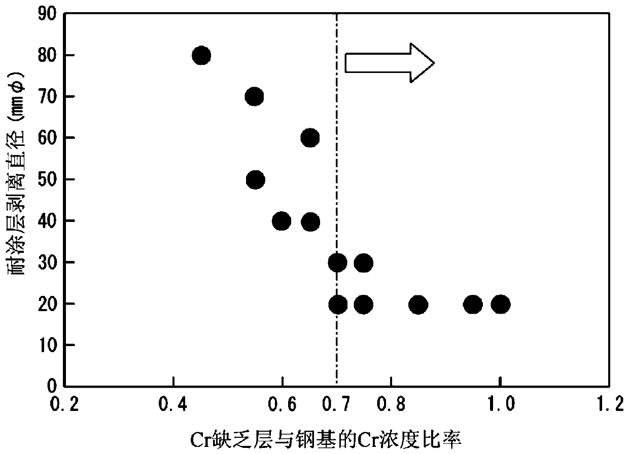
Provided is a grain-oriented electrical steel sheet having a forsterite coating film on a ferrite surface, wherein the grain-oriented electrical steel sheet has a Cr-depleted layer having a Cr concentration 0.70-0.90 times the Cr concentration in the ferrite at the boundary between the ferrite and the forsterite coating film, whereby the grain-oriented electrical steel sheet has transformer iron loss characteristics superior to the prior art.

Description

technical field [0001] The present invention relates to a grain-oriented electrical steel sheet and a manufacturing method thereof, in particular to a grain-oriented electrical steel sheet suitable for an iron core material of a winding transformer and a manufacturing method thereof. Background technique [0002] The iron loss of the grain-oriented electrical steel sheet assembled into a transformer (transformer iron loss) is inevitably greater than the iron loss of the grain-oriented electrical steel sheet in the original state of the product sheet (product sheet iron loss). The increase ratio of the iron loss is called a building factor (BF, building factor). This increase in iron loss is attributable to the processing strain introduced in the transformer assembly process, the generation of rotating magnetic flux that does not occur when evaluating the iron loss of a product plate, and the like. [0003] In order to remove processing strain, there is a stress relief annea...

Claims


Application Information

Patent Timeline
IPC IPC(8): C22C38/00C21D8/12C21D9/46C22C38/18H01F1/147C22C38/60
CPCC21D8/1255C21D8/1272C21D8/1283C21D8/1288C22C38/00C22C38/18C22C38/60C23C28/3455H01F1/147C21D1/72C21D3/04C21D8/1266C21D8/12H01F1/16C23C22/00C21D6/004C21D6/005C21D6/008C21D8/005C21D9/46C22C38/001C22C38/002C22C38/008C22C38/04C22C38/34C22C38/44C22C2202/02H01F1/14791H01F27/245H01F41/0233C22C38/02
Inventor 大村健井上博贵千田邦浩冈部诚司
Owner JFE STEEL CORP
Learn More