Multifunctional weeding rotary cultivator for orchard
A multi-functional, rotary tiller technology, applied to harvesters, agricultural machinery and tools, cutters, etc., can solve problems such as difficulty, different thickness, and accidental damage to trees, so as to increase the stability of motion and improve work efficiency , reduce the effect of wrapping grass
- Summary
- Abstract
- Description
- Claims
- Application Information
AI Technical Summary
Problems solved by technology
Method used
Image
Examples
Embodiment 1
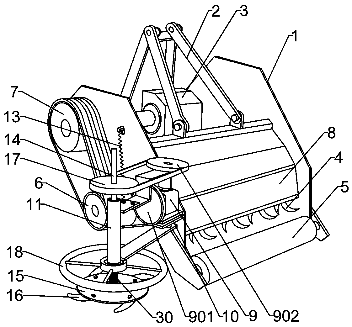
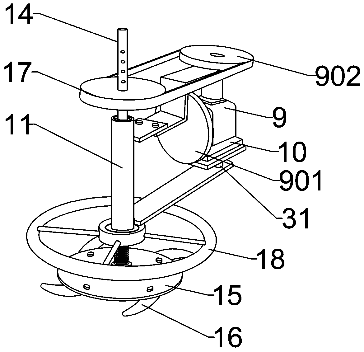
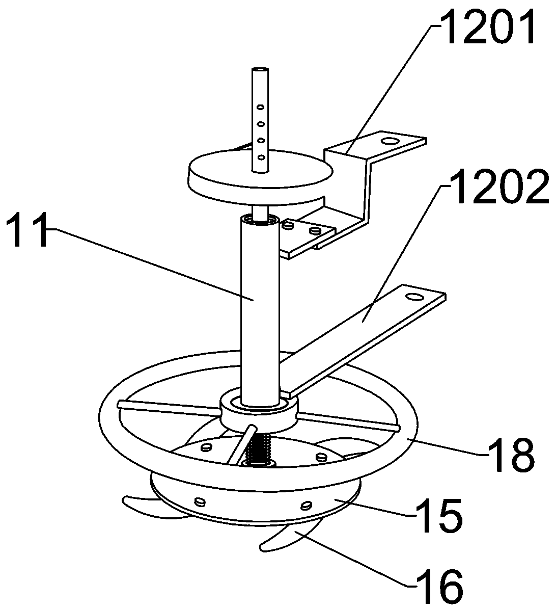
[0022] Embodiment 1: a kind of orchard multifunctional weeding rotary tiller, such as Figure 1-6 As shown, it includes a frame 1 and a rotary cultivating mechanism and a weeding mechanism arranged on the frame 1. Two pairs of booms 2 are installed on the upper end of the frame 1, and the frame passes through the traveling mechanism at the front end of the boom 2 and the frame 1. (Tractor, etc.) connected, pulled forward by the walking mechanism. A drive motor 3 is installed on the frame 1, the output shaft of the drive motor 3 stretches out from the outside of the frame and is fitted with an output pulley 7; a rotary cultivator shaft and a crushing roller 5 are horizontally installed on the inside of the frame, Wherein the shaft of the rotary tiller and the crushing roller 5 are parallel to each other, and one end of the shaft of the rotary tiller extends out of the frame and is equipped with a double belt pulley 6, and the double belt pulley 6 passes through the output pulle...
Embodiment 2
[0027] Embodiment 2: A kind of orchard multi-functional weeding rotary tiller in this embodiment is described with different point centers from Embodiment 1.
[0028] In this embodiment, the end portion of the drive shaft positioned below the cutterhead 15 is also provided with a horizontal column hole 28, and the horizontal column hole is pierced with an anti-falling steel wire 29. For further protection, prevent accidents when the cutter head falls off during the work process.
[0029] In this embodiment, a buffer spring 30 is set on the outer wall of the transmission shaft 14 between the avoidance retainer 18 and the cutter head 15, the upper end of the buffer spring is against the lower end surface of the support sleeve 11, and the lower end of the buffer spring is against the knife On the upper end surface of the disc boss 21, the buffer spring 30 can further eliminate the vibration of the cutter disc 15 during cutting and weeding operations, increase the stability of the...
PUM
 Abstract
Description
Claims
Application Information
 - R&D
- Intellectual Property
- Life Sciences
- Materials
- Tech Scout
- Unparalleled Data Quality
- Higher Quality Content
- 60% Fewer Hallucinations
Browse by: Latest US Patents, China's latest patents, Technical Efficacy Thesaurus, Application Domain, Technology Topic, Popular Technical Reports.
© 2025 PatSnap. All rights reserved.Legal|Privacy policy|Modern Slavery Act Transparency Statement|Sitemap|About US| Contact US: help@patsnap.com


