
Side Spray Cooling Mechanism and Cooling Method of Hot Forging Die Frame

A cooling mechanism and hot forging die technology, applied in heating/cooling equipment, forging/pressing/hammer devices, metal processing equipment, etc., can solve the problems of workshop working environment pollution, untimely cooling, surge, etc., and achieve optimized cooling effect , The cooling process is stable, and the effect of simplifying the cooling process

Active Publication Date: 2020-07-10
安徽康尼精密机械有限公司
View PDF7 Cites 0 Cited by
  • Summary
  • Abstract
  • Description
  • Claims
  • Application Information

AI Technical Summary

Problems solved by technology

The disadvantage of this lubrication method is that there will be a large amount of graphite powder, which will cause environmental pollution in the workshop
[0003] In the hot forging form with a large amount of water, the mold does not need to be heated, but it needs to be cooled in time to keep the mold at room temperature during the production process and rely on water vapor for lubrication during rapid forming. If the cooling is not timely, the mold and forgings will appear sticky. The phenomenon of contact phenomenon and the surge of ejection force greatly reduces the life of the mold, and sometimes even causes the product to fail to form. Therefore, cooling in the die and punch cooling devices are required for timely cooling
The disadvantage of this cooling method, which usually uses a hose to directly spray a large amount of cooling water, is that when the cooling water is used, the cooling hose is affected by the up and down movement of the mold frame, and the cooling is often not timely, which is time-consuming and laborious, and the effect is not good. , most of the hoses need to extend into the forming area of ​​the mold base, which makes the walking beam unable to realize full automation and often alarms

Method used


Image

  • Side Spray Cooling Mechanism and Cooling Method of Hot Forging Die Frame
  • Side Spray Cooling Mechanism and Cooling Method of Hot Forging Die Frame
  • Side Spray Cooling Mechanism and Cooling Method of Hot Forging Die Frame

Examples


Embodiment 1

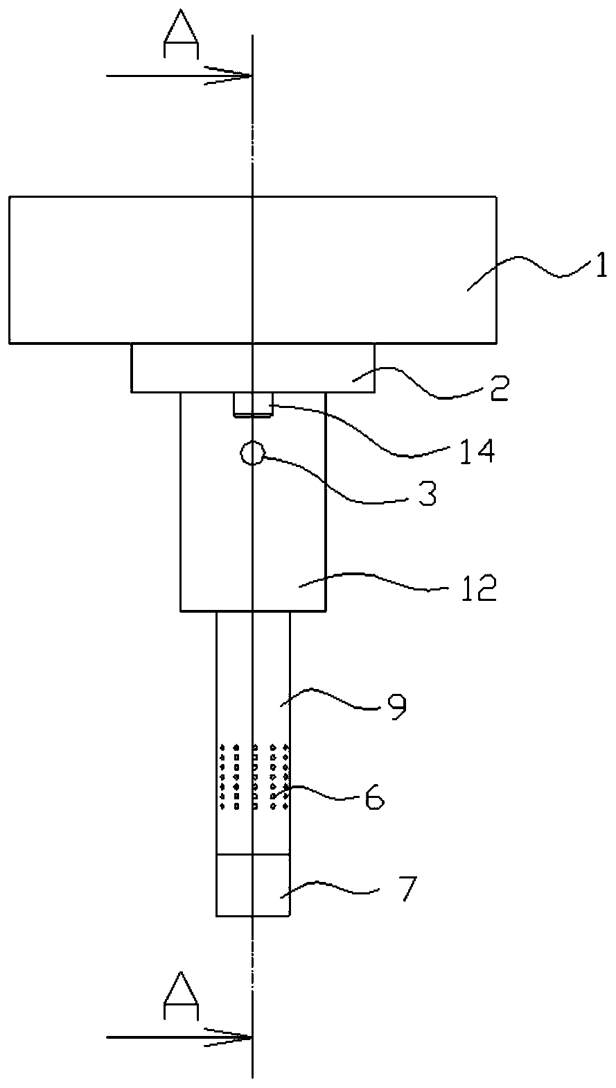
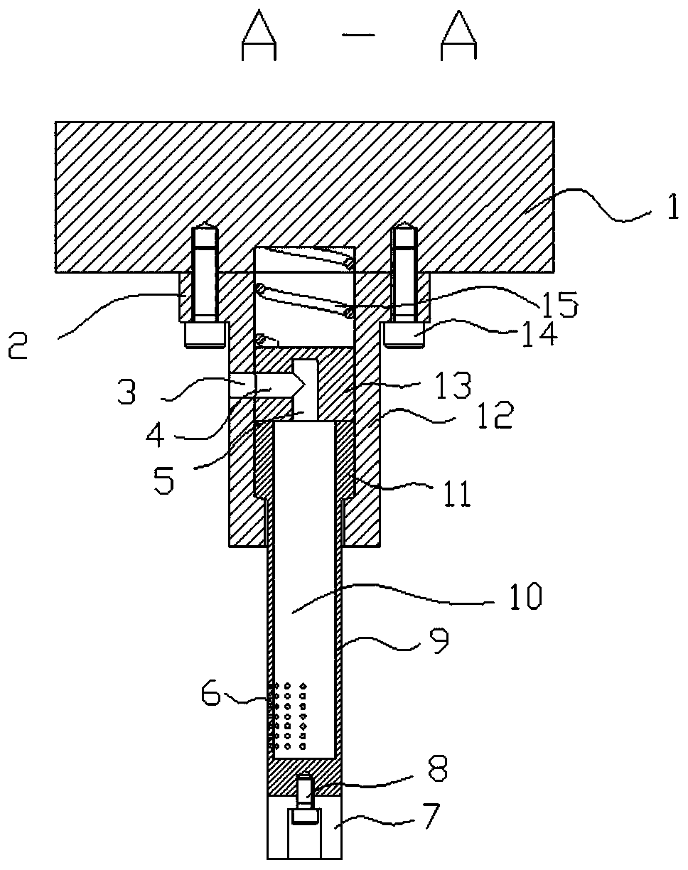
[0034] This hot forging die frame uses a side spray cooling mechanism, including a fixed sleeve 12 and a nozzle module 9, the fixed sleeve 12 is axially penetrated through the hollow, the side wall of the fixed sleeve 12 is provided with a diversion port 3, and the upper part of the nozzle module 9 is the same as The shaft sleeve is set in the fixed sleeve 12, the lower part of the nozzle module 9 extends outside the fixed sleeve 12, the upper edge of the fixed sleeve 12 is provided with a flange 2, and the flange 2 is provided with several through holes through which the screws 14 pass Through holes, and screwed into the upper mold template 1, the fixing sleeve 12 is fixed below the upper mold template 1.

[0035] The axial center of the spray head module 9 is provided with a spray chamber 10, the upper end of the spray chamber 10 is an open end, and the lower end is a blind end, and the side wall of the spray head module 9 near the bottom is provided with several nozzles 6. ...

Embodiment 2

[0042] In order to protect the bottom of the nozzle module 9 and prevent hard impact during use, a protective cover 7 is provided under the nozzle module 9, and the protective cover 7 can be made of a material with certain elasticity to play a buffering effect. The protective cover 7 is in the shape of a cylinder, and the axial center of the protective cover 7 is provided with a screw plug hole, and the bolt 8 passes through the screw plug hole and is tightened on the lower end of the nozzle module 9 to fix the protective cover 7 .

Embodiment 3

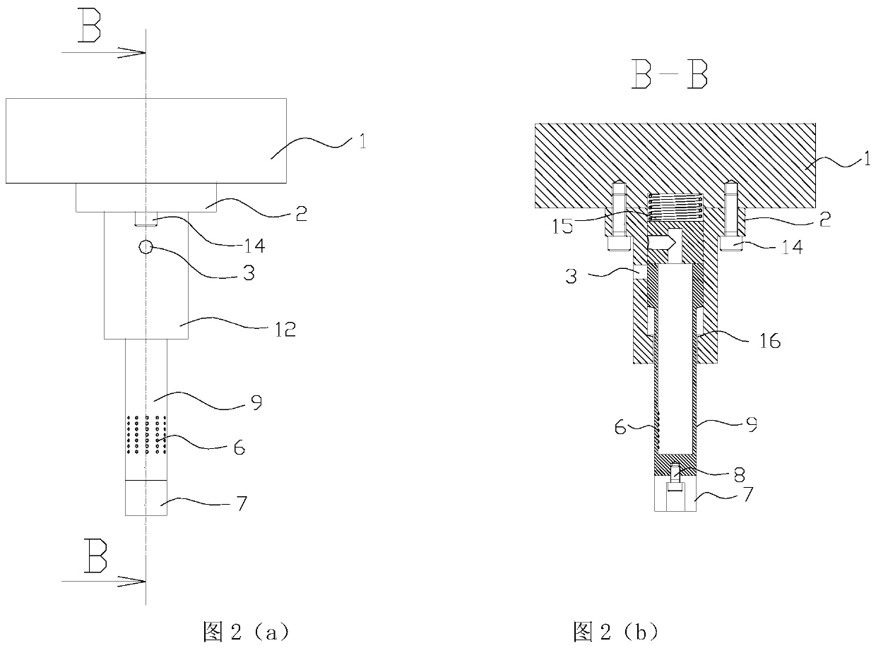
[0044] In order to be able to install a spring 15 of sufficient length, a groove is provided in the place where the upper die template 1 contacts the spring 15, and the top of the spring 15 is located in the groove. The aperture of the groove is consistent with the aperture of the fixed sleeve 12 .

[0045] Attached Figure 1(a), Figure 1(b) and Attached figure 2 The two states of the present invention are given, and the application scenarios of the present invention are further described below in combination with methods.

[0046] A side spray cooling method for a hot forging die frame, comprising the following steps:

[0047] Step 1: Install the side spray cooling mechanism: Install the above-mentioned side spray cooling mechanism under the upper mold template 1 of the hot forging die frame, and let the nozzle 6 face the punch, and the distance between the punch and the nozzle 6 is smaller than the nozzle 6. The stroke of the coolant to ensure that the coolant can be sprayed ...


PUM


Abstract

The invention discloses a side-spraying cooling mechanism and method for a hot-forging mould frame. The side-spraying cooling mechanism comprises a fixed sleeve and a spray head module, wherein the upper part of the spray head module is coaxially arranged in the fixed sleeve in a sleeved mode; the lower part of the spray head module extends to a position below the fixed sleeve; a spray nozzle is arranged on the side wall of one side of the spray head module; a spray cavity is arranged in the spray head module; a guide hole is formed in the side wall of the fixed sleeve; a guide block is arranged above the spray head module; the guide block is equipped with a perpendicular guide cavity and a horizontal guide cavity, which are through; and a spring is arranged above the guide block. The cooling method comprises the following steps: enabling the guide hole to be flush to the horizontal guide cavity in a mould-opening state, introducing cooling liquid into the guide cavity from the guide hole, spraying the cooling liquid from the spray nozzle, directly ejecting the cooling liquid onto a punch, enabling the guide hole to be staggered from the horizontal guide cavity after mould-closing,and stopping spraying cooling liquid. The side-spraying cooling mechanism is mounted under an upper mould moulding board of the hot-forging mould frame, optimizes the cooling effect, prolongs the service life of the mould, is better in cooling effect, and is more convenient and quick.

Description

technical field [0001] The invention relates to a side spray cooling mechanism and a cooling method of a hot forging die frame, belonging to the technical field of hot forging cooling. Background technique [0002] In traditional hot forging, the mold needs to be heated to about 200°C, and the mold is lubricated by spraying graphite suspension on the surface of the mold. After evaporation, the residual graphite acts as a lubricating medium at high temperature. The disadvantage of this lubrication method is that there will be a large amount of graphite powder, which will cause environmental pollution in the workshop. [0003] In the hot forging form with a large amount of water, the mold does not need to be heated, but it needs to be cooled in time to keep the mold at room temperature during the production process and rely on water vapor for lubrication during rapid forming. If the cooling is not timely, the mold and forgings will appear sticky. The contact phenomenon and th...

Claims


Application Information

Patent Timeline
Patent Type & Authority Patents(China)
IPC IPC(8): B21K29/00
CPCB21K29/00
Inventor 王遥袁天宇
Owner 安徽康尼精密机械有限公司
Learn More