
Machining lathe for bearing rings

A technology of bearing rings and lathes, applied in metal processing, metal processing equipment, metal processing machinery parts, etc., can solve the problems of increasing the workload of operators and reducing production efficiency, so as to facilitate cleaning and collection, improve production efficiency, Avoid out-of-conduction effects

Active Publication Date: 2019-08-02
XINCHANG COUNTY XINXIANGYU BEARING
View PDF7 Cites 10 Cited by
  • Summary
  • Abstract
  • Description
  • Claims
  • Application Information

AI Technical Summary

Problems solved by technology

[0004] The above-mentioned existing technical solutions have the following defects: because the cutting lathe requires the operator to manually place the bearing outer ring, and fix the bearing outer ring through the internal expansion pin and the top piece, thereby increasing the workload of the operator and reducing production efficiency

Method used


Image

  • Machining lathe for bearing rings
  • Machining lathe for bearing rings
  • Machining lathe for bearing rings

Examples


Embodiment Construction

[0036] The present invention will be described in further detail below in conjunction with the accompanying drawings.

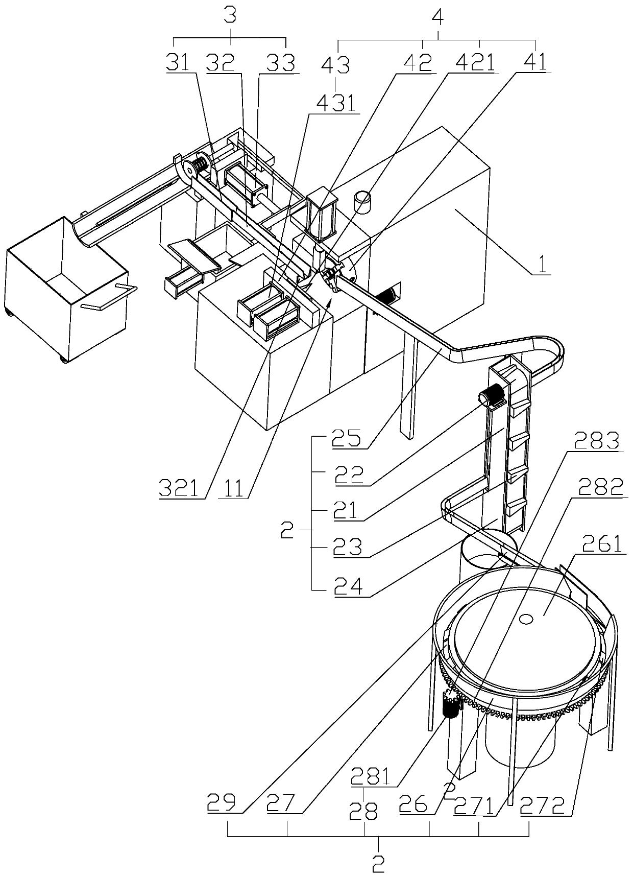
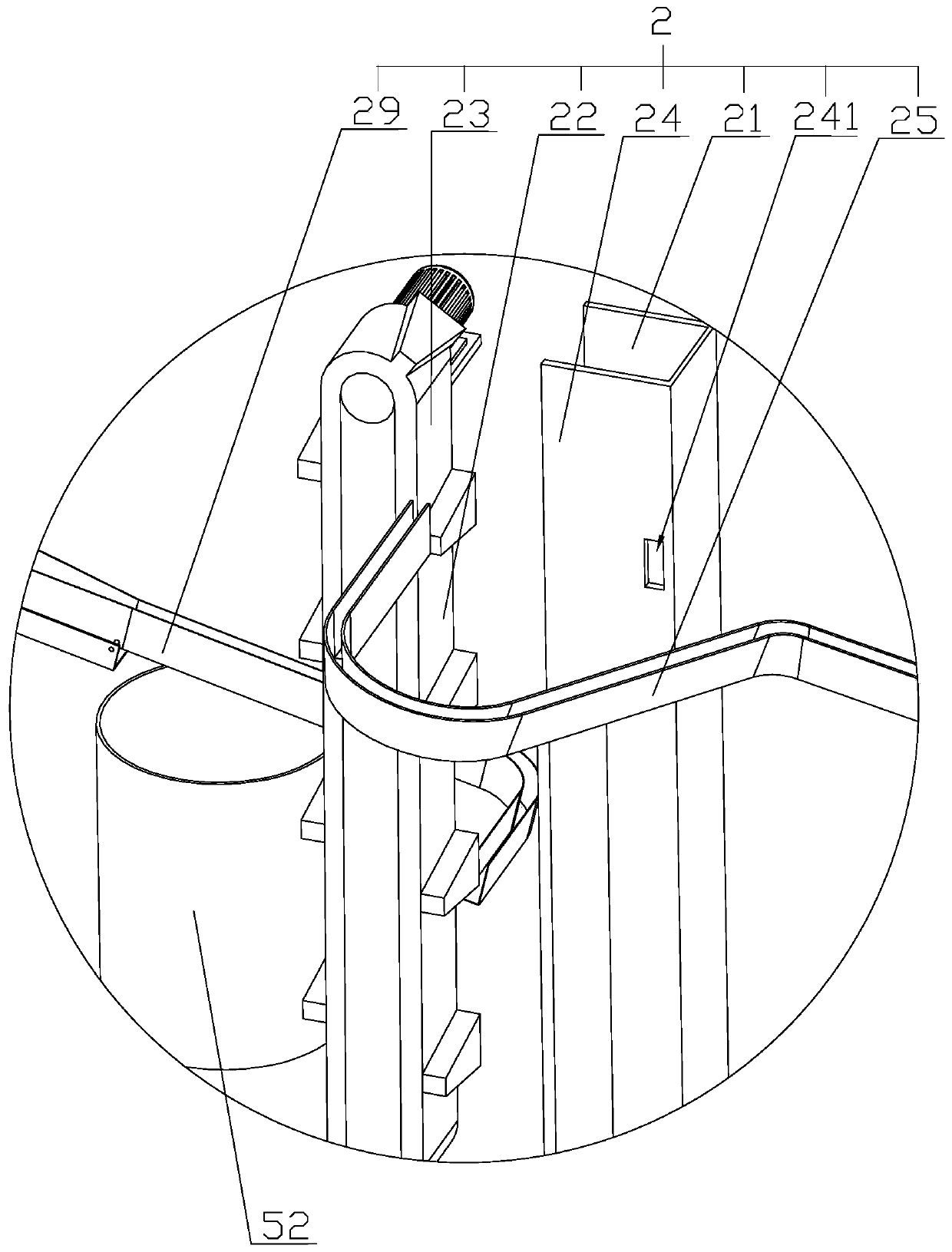
[0037] refer to figure 1 , figure 2 , is a bearing ring processing lathe disclosed in the present invention, including a machine body 1, and also includes a feeding mechanism 2, a cutting mechanism 4, and a material discharging mechanism 3 sequentially arranged on the body 1 along the bearing ring transmission direction. The feeding mechanism 2 is used to arrange the scattered bearing rings in an orderly manner and send them one by one into the cutting mechanism 4 for cutting processing, and then send the processed bearing rings away from the processing position through the discharging mechanism 3 for sorting and collecting.

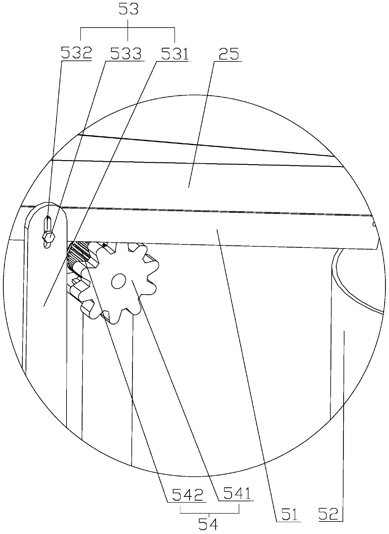
[0038] The feeding mechanism 2 includes a screening basin 26, a discharge plate 261 arranged on the screening basin 26, a booster ring 27 distributed along the circumferential direction of the discharge plate 261 and connected in rota...


PUM


Abstract

The invention relates to a machining lathe for bearing rings, and relates to the technical field of bearing machining equipment. The machining lathe comprises a machine body and further comprises a feeding mechanism, a cutting mechanism and a discharging mechanism. The feeding mechanism, the cutting equipment and the discharging mechanism are sequentially arranged on the machine body in the conveying direction of the bearing rings. The feeding mechanism comprises a screening basin, a conical unloading plate arranged on the screening disc, boosting rings distributed in the circumferential direction of the unloading plate and rotationally connected with the screening basin, a drive part arranged on the machine body and used for driving the boosting rings to rotate, and a feeding pipe tangentto the peripheral side walls of the boosting rings and communicating with the boosting rings. One end of the feeding pipe communicates with a cutting lathe, the width of the feeding pipe is consistent with the heights of the bearing rings, ring slots communicating with the peripheral side walls are formed in the top faces of the boosting rings in the circumferential directions of the boosting rings, the bottom walls of the ring slots are inclined, and the inclined surfaces face the side away from the unloading plate. The machining lathe has the effect that feeding of the bearing rings is facilitated in order to improve the production efficiency.

Description

technical field [0001] The invention relates to the technical field of bearing processing equipment, in particular to a lathe for processing bearing rings. Background technique [0002] At present, bearings are an important part of contemporary mechanical equipment. Its main function is to support the mechanical rotating body, reduce the friction coefficient during its movement, and ensure its rotation accuracy. General bearings mainly include bearing rings, bearing inner rings, and balls. The balls are placed between the bearing rings and the bearing inner ring. Lower coefficient of friction, thereby reducing mechanical wear and energy consumption. The bearing ring is a ring-shaped part of a radial rolling bearing with one or several raceways, which is processed by a lathe. [0003] The Chinese utility model whose notification number is CN208230857U discloses a bearing outer ring face cutting lathe, which belongs to the technical field of bearing outer ring processing eq...

Claims


Application Information

Patent Timeline
Patent Type & Authority Applications(China)
IPC IPC(8): B23B5/00B23B15/00B23Q7/00B23Q11/00
CPCB23B5/00B23Q7/00B23Q11/0042
Inventor 石槐灿徐玉宝张忠海张金聪陈忠祥石宇翔李辉
Owner XINCHANG COUNTY XINXIANGYU BEARING
Learn More