Screw screwing machine

A screw machine and screw driver technology, applied in metal processing, metal processing equipment, manufacturing tools, etc., can solve problems such as low work efficiency, complex procedures, and complex structures, so as to control costs, improve synchronization rate and efficiency, and improve production efficiency. Effect

Inactive Publication Date: 2019-08-02
CHANGZHOU COLLEGE OF INFORMATION TECH
View PDF0 Cites 2 Cited by
  • Summary
  • Abstract
  • Description
  • Claims
  • Application Information

AI Technical Summary

Problems solved by technology

From the above working mechanism, it can be seen that firstly, the screwdriver needs to screw in the screws one by one, which is inefficient. Secondly, although the circuit is fixed, the program needs to be written according to the position of each bolt in each workpiece. The program is complicated. Finally, after each movement of the manipulator Whether the positioning is accurate or not needs to be judged and fed back by the corresponding sensor electrical components. Although it can be done with the current technology, the cost is high and the structure is complicated.

Method used


Image

  • Screw screwing machine
  • Screw screwing machine
  • Screw screwing machine

Examples


Embodiment 1

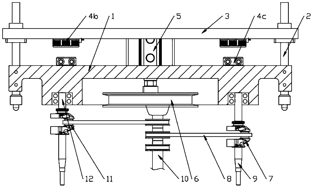
[0040] Use the electromagnet 4b and the metal block 4c as the clutch assembly to perform the screwing operation, and the operation steps are as follows:

[0041] Step 1. The workpiece is moved to the bottom of the substrate 1;

[0042] Step 2. Disconnect the power supply of electromagnet 4b;

[0043] Step 3. The metal block 4c loses its magnetic adsorption;

[0044] Step 4. Substrate 1 falls;

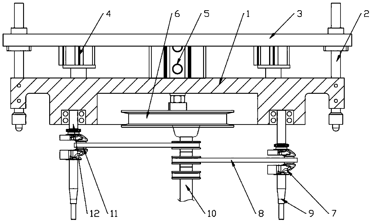
[0045] Step 5. The functional block 9 falls synchronously, and its cutter head is located at the screw;

[0046] Step 6. Start the motor 5, and the motor 5 drives the driving wheel 6 to rotate;

[0047] Step 7. The guide post 10 revolves around the center of the drive wheel;

[0048] Step 8. The connecting rod 8 rotates synchronously;

[0049] Step 9. The connecting rod 8 drives the driven wheel 7 and the connecting ring 12 to rotate synchronously through the pivot pin 11;

[0050] Step 10. The driven wheel 7 drives the screwdriver 9 to rotate;

[0051] Step 11. When the head of ...

Embodiment 2

[0059] Use the cylinder as the clutch assembly to carry out the screwing operation, and the operation steps are as follows:

[0060] Step 1. The workpiece is moved to the bottom of the substrate 1;

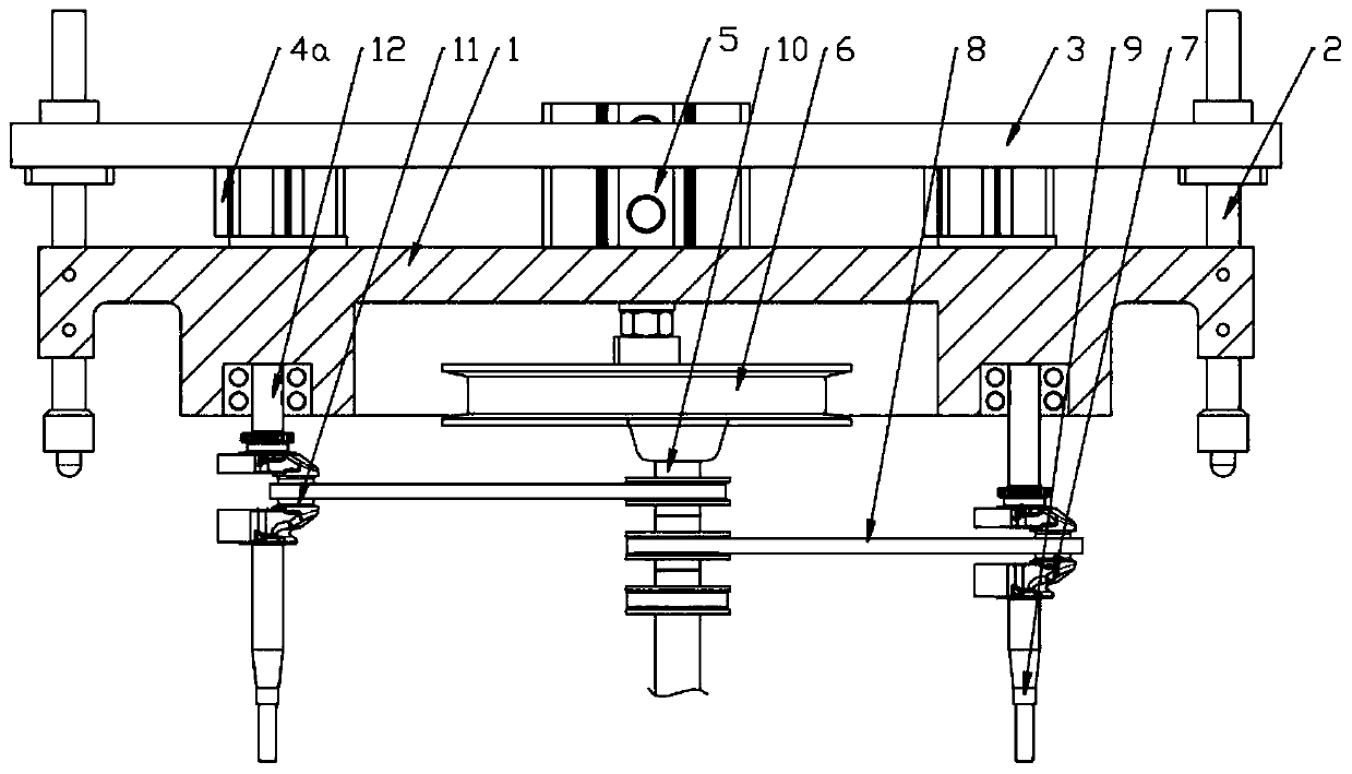
[0061] Step 2. Start cylinder 4a;

[0062] Step 3. The cylinder shaft of cylinder 4a moves downward;

[0063] Step 4. Substrate 1 falls;

[0064] Step 5. The functional block 9 falls synchronously, and its cutter head is located at the screw;

[0065] Step 6. Start the motor 5, and the motor 5 drives the driving wheel 6 to rotate;

[0066] Step 7. The guide post 10 revolves around the center of the drive wheel;

[0067] Step 8. The connecting rod 8 rotates synchronously;

[0068] Step 9. The connecting rod 8 drives the driven wheel 7 and the connecting ring 12 to rotate synchronously through the pivot pin 11;

[0069] Step 10. The driven wheel 7 drives the screwdriver 9 to rotate;

[0070] Step 11. When the head of the screwdriver 9 rotates synchronously, it fits with the s...

Embodiment 3

[0078] Installation of screwdriver 9:

[0079] Step 1. According to the workpiece, select a screw brush 9 with a suitable length and suitable for the cutter head;

[0080] Step 2. Insert the screwdriver 9 into the driven wheel 7 from bottom to top;

[0081] Step 3. Connect the through hole between the upper part of the screwdriver 9 and the side end of the driven wheel 7;

[0082] Step 4. Screw in the screw pin 13;

[0083] Step 5. Put the gasket 15 on the two ends of the screw pin 13;

[0084] Step 6. Screw the nuts 14 on both ends of the screw pin 13 and tighten them.


PUM


Abstract

The invention discloses a screw screwing machine. The screw screwing machine comprises a base plate, wherein the base plate is a rectangular metal plate which is arranged in the horizontal direction,four corners of the base plate are provided with optical shafts in a penetrating mode, the tops of the optical shafts are provided with a fixing plate, a separation and reunion assembly is installed between the fixing plate and the base plate, a motor is installed on the top surface of the base plate, and a driving wheel and a driven wheel are arranged on the bottom surface of the base plate. Thescrew screwing machine has the beneficial effects that the position of a screwdriver is matched with a workpiece, only the screwdriver needs to be moved in the vertical direction, the rotation and driving of the screwdriver can be achieved, and the structure is simple, all screws are screwed once, so that the production efficiency is improved, only one motor is needed to screw all screws, the costis further controlled, and the screwing synchronous rate and efficiency are improved.

Description

technical field [0001] The invention relates to the field of assembly machinery, in particular to a screw driving machine. Background technique [0002] In the field of assembly machinery, screwing and bolting are the most commonly used assembly and fixing methods. In the prior art, the working mechanism of the automatic screw-tightening machine is to fix the electric screwdriver on the manipulator, generally a three-axis gantry manipulator, and then design the electric control circuit according to the structure of the electric screwdriver and the manipulator, and then based on the workpiece The position of the screw is written into the program, so that the manipulator controls the screwdriver, and the screws and bolts are screwed in one by one in a programmed manner. From the above working mechanism, it can be seen that firstly, the screwdriver needs to screw in the screws one by one, which is inefficient. Secondly, although the circuit is fixed, the program needs to be wr...

Claims


Application Information

Patent Timeline
Patent Type & Authority Applications(China)
IPC IPC(8): B23P19/06
CPCB23P19/06
Inventor 汪涵
Owner CHANGZHOU COLLEGE OF INFORMATION TECH
Why Eureka
Try Eureka