Construction method of basement pile-wall integrated structure system

A construction method and technology for basement exterior walls, applied in underwater structures, infrastructure engineering, excavation, etc., can solve problems such as waste of resources, large amount of supporting materials, and unfavorable environmental protection building resources.

Inactive Publication Date: 2019-08-02
GUANGZHOU URBAN PLANNING & DESIGN SURVEY RES INST
View PDF6 Cites 13 Cited by
  • Summary
  • Abstract
  • Description
  • Claims
  • Application Information

AI Technical Summary

Problems solved by technology

Conventional foundation pit support engineering is generally a temporary project, the support structure is buried deeply, and the amount of support materials is large. Solid obstacles such as foundation pit support piles and continuous walls are left around the structure, causing a lot of waste of resources, which is not conducive to environmental protection and saving of construction resources
[0003] Moreover, since the support piles are used as a temporary support structure, there will be enough construction space between the basement exterior wall and the support piles during construction. Generally, there is a clear space of 1 to 2 meters for the basement to be built in this space. External wall waterproofing, formwork support, and tying of steel bars, etc., but it cannot solve the problem that the space between the basement external wall and the supporting piles is so small that construction personnel cannot enter between the two for waterproofing construction, resulting in the waterproof structure of the basement. The promotion of the system is subject to certain restrictions

Method used


Image

  • Construction method of basement pile-wall integrated structure system
  • Construction method of basement pile-wall integrated structure system
  • Construction method of basement pile-wall integrated structure system

Examples


Embodiment Construction

[0030] The specific implementation manners of the present invention will be further described in detail below in conjunction with the accompanying drawings and embodiments. The following examples are used to illustrate the present invention, but are not intended to limit the scope of the present invention.

[0031] In the description of the present invention, it should be understood that the orientation or positional relationship indicated by the terms "upper", "lower", "left", "right", "top", "bottom" etc. Orientation or positional relationship is only for the convenience of describing the present invention and simplifying the description, and does not indicate or imply that the referred device or element must have a specific orientation, be constructed and operated in a specific orientation, and thus should not be construed as a limitation of the present invention.

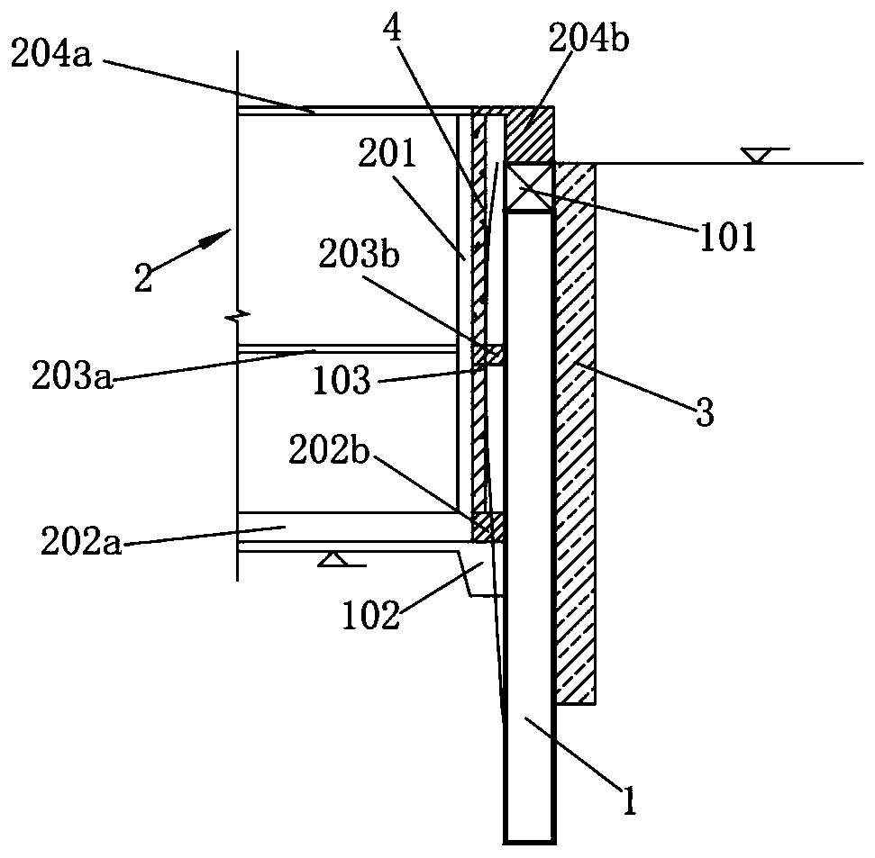
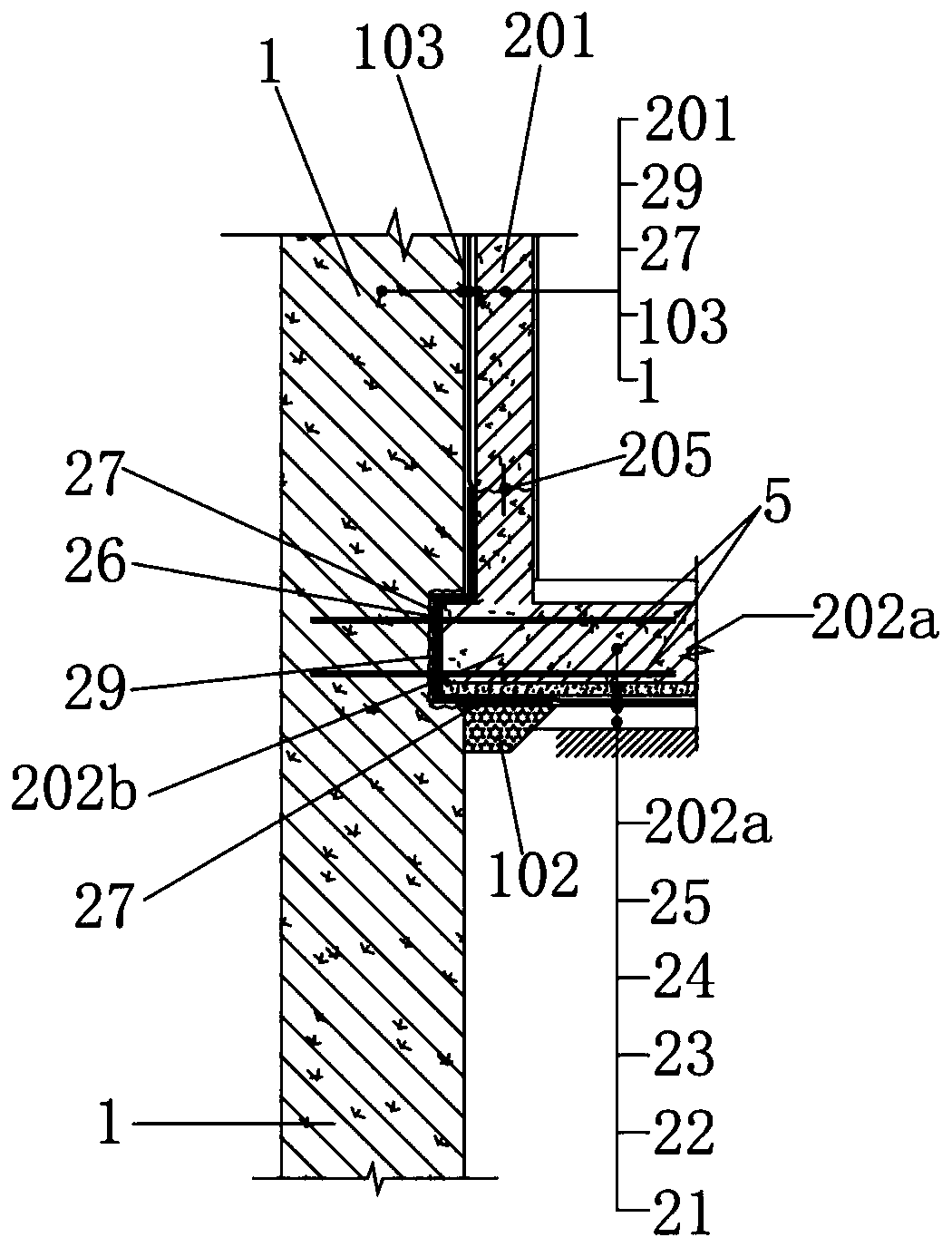
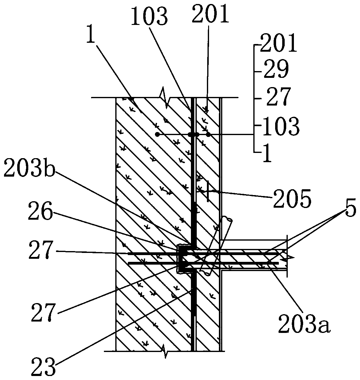
[0032] combine Figure 1~4 As shown, schematically shows a construction method of a basement 2-pile-wall-in-...


PUM


Abstract

The invention relates to the technical field of building construction. The invention discloses a construction method of a basement pile-wall integrated structure system. A bottom plate connecting plate, a floor slab connecting plate and a top plate connecting plate are arranged between foundation pit supporting piles and a basement exterior wall. The bottom plate connecting plate, the floor slab connecting plate and the top plate connecting plate are respectively connected with a bottom plate, a floor slab and a top plate of a basement through steel bar planting bars and are poured simultaneously; the foundation pit supporting piles and the basement structure are stably connected, the foundation pit supporting piles are fully used as one part of the permanent structure in the permanent usestage, and the advantages of protecting the environment, saving building resources, shortening the construction period and the like are achieved; meanwhile, basement waterproof operation is carried out while the construction steps of bar planting, formwork erecting, steel bar binding and the like are carried out, all floors are waterproof layer by layer and poured layer by layer, the basement non-poured space can be fully utilized for waterproof construction operation, the waterproof construction is not limited by the space between a basement outer wall and a supporting pile, and the waterproof effect is guaranteed.

Description

technical field [0001] The invention relates to the technical field of building construction, in particular to a construction method of a pile-wall integrated structural system in a basement. Background technique [0002] With the continuous development of my country's construction industry, there are more and more super large and super deep foundation pit projects. Conventional foundation pit support engineering is generally a temporary project, the support structure is buried deeply, and the amount of support materials is large. Solid obstacles such as foundation pit support piles and continuous walls are left around the structure, resulting in a large waste of resources, which is not conducive to environmental protection and saving of construction resources. [0003] Moreover, since the support piles are used as a temporary support structure, there will be enough construction space between the basement exterior wall and the support piles during construction. Generally, t...

Claims


Application Information

Patent Timeline
Patent Type & Authority Applications(China)
IPC IPC(8): E02D17/04E02D29/045E02D31/02
CPCE02D17/04E02D29/045E02D31/02E02D31/025E02D2250/0023
Inventor 邓国基刘伟彭卫平温忠义刘志方黄凯湘
Owner GUANGZHOU URBAN PLANNING & DESIGN SURVEY RES INST
Why Eureka
Try Eureka