Rubber fatigue tensile test bench and rubber fatigue tensile test method

A tensile test and rubber technology, applied in the direction of applying stable tension/pressure to test the strength of materials, to achieve the effects of strong controllability, reduced inertial impact, and simple structure

Inactive Publication Date: 2019-08-02
BEIJING FORESTRY UNIVERSITY
View PDF3 Cites 6 Cited by
  • Summary
  • Abstract
  • Description
  • Claims
  • Application Information

AI Technical Summary

Problems solved by technology

The technical solution adopts a top-down structure, and there is little description of how the control system is applied

Method used


Image

  • Rubber fatigue tensile test bench and rubber fatigue tensile test method
  • Rubber fatigue tensile test bench and rubber fatigue tensile test method
  • Rubber fatigue tensile test bench and rubber fatigue tensile test method

Examples


Embodiment Construction

[0028] First, the specific structure of the rubber tensile test bench of the present invention will be described in detail below.

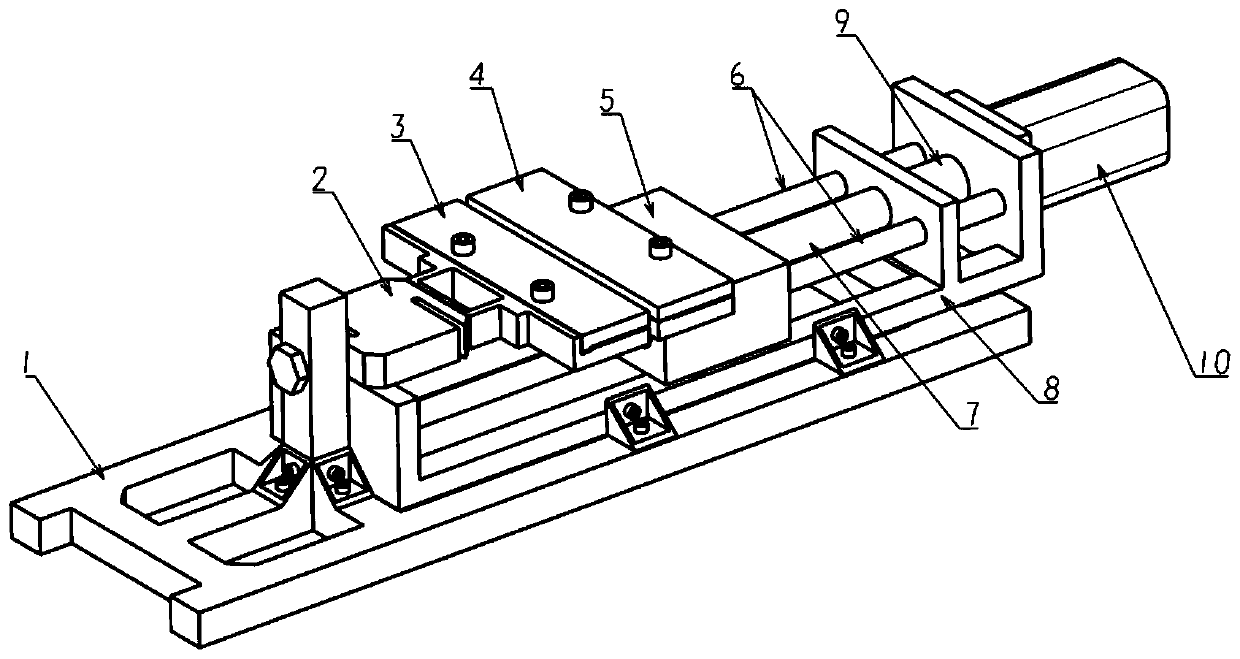
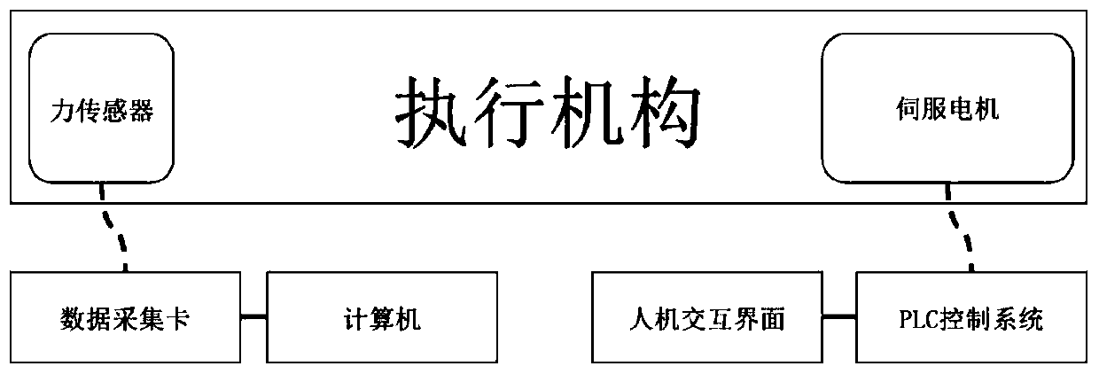
[0029] see figure 1 , in an embodiment of the present invention, a rubber fatigue tensile test bench is composed of three parts: an actuator, a data acquisition system, and a control system. The actuator includes an overall fixing frame 1, a force sensor 2, a left clamp 3, and a right clamp 4. Sliding table 5, support rod 6, lead screw 7, sliding table base 8, coupling 9, servo motor 10; the left clamp 3 is installed on the force sensor 2 through a fixed bracket and bolts, and the force sensor 2 is mounted on the force sensor 2 through the bolts Installed on the sensor installation column of the overall fixed frame 1; the right fixture 4 is installed on the slide table 5 through bolts, and a threaded hole is processed in the middle of the slide table 5, and there is a light hole on each side of the threaded hole; the slide table 5 is installed on ...


PUM


Abstract

The invention relates to a rubber fatigue tensile test bench and a rubber fatigue tensile test method. The test bench is composed of three parts, that is, an actuator, a data collection system and a control system, and the actuator comprises an overall fixing fixture, a force sensor, a left fixture, a right fixture, a sliding table, a support rod, a lead screw, a sliding table base, a coupling anda servo motor; the control system comprises a data collection card, a computer, a human-computer interaction interface and a PLC control system; the control system controls the rotation speed and direction of the servo motor through the PLC control system, so as to control the left fixture and the right fixture to load a rubber test sample; the rubber fatigue tensile test bench provided by the invention is simple in overall system composition, high in maneuverability and good in human-computer interaction; and further, a rubber fatigue tensile model obtained by using the rubber fatigue tensile test method provided by the invention is more accurate compared with that in the prior art.

Description

technical field [0001] The invention relates to a rubber fatigue tensile test bench and a rubber fatigue tensile test method. Background technique [0002] As an irreplaceable elastic material, rubber has been used for more than 160 years and has been widely used in national defense and economic construction. Rubber is not only an indispensable substance in life, but also a high-performance and functional material necessary for the development of high-tech. In order to achieve the purpose of vibration reduction, noise reduction, flexibility and wear resistance, rubber is often compounded with metal to make elastic elements, which are widely used in many high-precision fields. Rubber components usually work under cyclic stress, and the fatigue fracture performance of rubber materials often determines the fatigue life of components. With the increasingly harsh service conditions of rubber products, the problem of rubber fatigue failure has become increasingly prominent and n...

Claims


Application Information

Patent Timeline
Patent Type & Authority Applications(China)
IPC IPC(8): G01N3/08
CPCG01N3/08
Inventor 王青春王渊雍占福
Owner BEIJING FORESTRY UNIVERSITY
Why Eureka
Try Eureka