Fast DC switch and control method thereof

A DC switch, fast technology, applied in the direction of electrical components, emergency protection circuit devices, etc., can solve the problems of long breaking time of small current, difficulty of breaking small current, breakdown of mechanical fracture, etc., to improve breaking capacity, fracture Good insulation recovery and fast breaking speed

Pending Publication Date: 2019-08-02
陕西秦屿电器有限公司
View PDF0 Cites 1 Cited by
  • Summary
  • Abstract
  • Description
  • Claims
  • Application Information

AI Technical Summary

Problems solved by technology

However, due to the existence of the pre-charged transfer capacitor, it is very difficult for the mechanical solution to break small currents. The current range is less than 1000 amperes for small currents, and greater than 1000 amperes for high currents
On the one hand, the large reverse injection current generated by the pre-charged capacitor in the case of small cur

Method used


Image

  • Fast DC switch and control method thereof
  • Fast DC switch and control method thereof
  • Fast DC switch and control method thereof

Examples


Embodiment 1

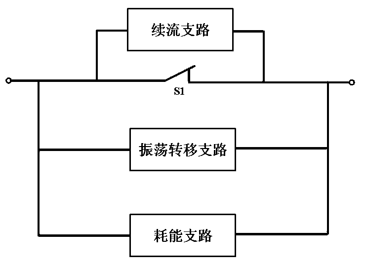
[0031] Such as figure 1 As shown, the fast DC switch in this embodiment includes a main current circuit, an oscillation transfer branch and an energy consumption branch.

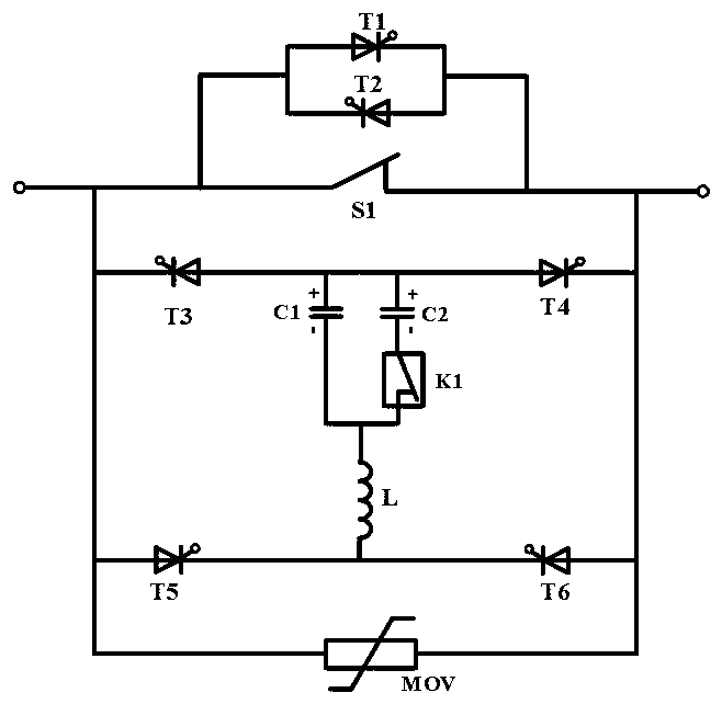
[0032] The circuit of the fast DC switch described in this embodiment is as follows figure 2 shown;

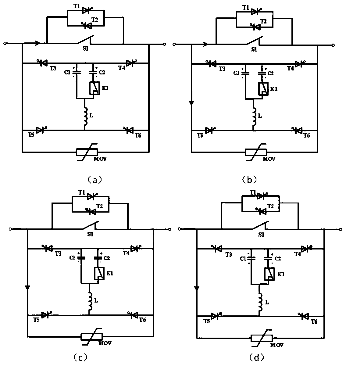
[0033] The specific process of breaking a small current is as follows: image 3 Shown:

[0034] (1), such as image 3 In the normal flow state shown in (a), the system current flows in from the outgoing terminal A1, and flows out from the outgoing terminal A2 after passing through the mechanical switch S1;

[0035] (2), such as image 3 As shown in (b), when the control system receives the rated breaking signal, the high-speed mechanical switch S1 is turned on to start arcing; the switch K1 is turned on;

[0036] (3), such as image 3 As shown in (c), after a delay, the trigger transfer branch is turned on, and the current is transferred to the transfer branch; when the main circuit current drops to ...

Embodiment 2

[0046] The fast DC switch structure described in this embodiment is as follows Figure 5 shown;

[0047] The concrete process of embodiment 2 breaking small electric current is as follows Figure 6 shown;

[0048] (1), such as Figure 6 In the normal flow state shown in (a), the system current flows in from the outgoing terminal A1, and flows out from the outgoing terminal A2 after passing through the mechanical switch S1;

[0049] (2), such as Figure 6 As shown in (b), when the control system receives the rated breaking signal, the high-speed mechanical switch S1 is turned on to start arcing; the switch K1 is turned on;

[0050] (3), such as Figure 6As shown in (c), after a delay, the trigger transfer branch and the freewheeling branch are turned on, and the current is transferred to the transfer branch; when the main circuit current drops to zero, the arc is extinguished, and the freewheeling branch is carried out through the freewheeling branch. ;

[0051] (4), suc...

Embodiment 3

[0058] The fast DC switch structure described in this embodiment is as follows Figure 8 shown;

[0059] Embodiment 3 The specific process of breaking the small current is as follows: Figure 9 shown;

[0060] (1), such as Figure 9 In the normal flow state shown in (a), the system current flows in from the outgoing terminal A1, and flows out from the outgoing terminal A2 after passing through the mechanical switch S1;

[0061] (2), such as Figure 9 As shown in (b), when the control system receives the rated breaking signal, the high-speed mechanical switch S1 is turned on to start arcing; the switch K1 is turned on;

[0062] (3), such as Figure 9 As shown in (c), after a delay, the trigger transfer branch is turned on, and the current is transferred to the transfer branch; when the main circuit current drops to zero, the arc is extinguished;

[0063] (4), such as Figure 9 As shown in (d), the small current continues to charge the transfer capacitor. When the capacit...


PUM


Abstract

The invention relates to a fast DC switch and a control method thereof and belongs to the field of an electric power switch. The fast DC switch is characterized by comprising a main current branch, anoscillation transfer branch and an energy dissipation branch, after the main current branch, the oscillation transfer branch and the energy consumption branch are connected in parallel, the three areled out through outlet ends A1 and A2. By controlling the action of an oscillation transfer branch switching switch K1, capacitance adjustment of an oscillation transfer branch pre-charging capacitoris realized; in the case of small current interruption, small current transfer is accomplished by a small capacitor, the break time is effectively shortened while breakage of a fracture can be prevented, and break reliability is improved; under high current break conditions, break is achieved by transferring the current through a large capacitor, the break capacity is improved, and the fast breakspeed and high reliability are achieved. The fast DC switch is advantaged in that advantages of low rated flow loss, good fracture insulation recovery, high break reliability and fast break speed inthe whole current range are achieved, and requirements of a current DC system for switch safety, reliability and economical property can be satisfied.

Description

technical field [0001] The invention belongs to the field of power switches, in particular to a fast direct current switch and a control method thereof. Background technique [0002] The DC power transmission and distribution system is an important development direction of the future power grid. It has the advantages of flexible operation mode, high power quality, stable system, and convenient access to distributed energy. The DC switch is the core equipment to ensure the safe and reliable operation of the DC distribution network. . At present, the mechanical DC switch based on pre-charged capacitor transfer has the advantages of large breaking current, low cost, and low loss, and has broad application prospects in future DC systems. However, due to the existence of the pre-charged transfer capacitor, it is very difficult for the mechanical solution to break small currents. The current range is less than 1000 amperes for small currents, and greater than 1000 amperes for hig...

Claims


Application Information

Patent Timeline
IPC IPC(8): H02H7/26
CPCH02H7/268H02H7/262
Inventor 任蔚
Owner 陕西秦屿电器有限公司
Why Eureka
Try Eureka