Photovoltaic group adjustment mechanism matching electric power new-energy charging pile

An adjustment mechanism and new energy technology, applied in the support structure of photovoltaic modules, photovoltaic modules, photovoltaic power generation, etc., can solve the problems of affecting the power generation effect of photovoltaic power generation panels, the inability to adjust photovoltaic power generation panels, and poor angle adjustment effects, etc., to improve The effect of light power generation, good adaptation to light needs, and the effect of avoiding wear and tear

Inactive Publication Date: 2019-08-02
赵瑞霞
View PDF10 Cites 0 Cited by
  • Summary
  • Abstract
  • Description
  • Claims
  • Application Information

AI Technical Summary

Problems solved by technology

[0006] In order to solve the above technical problems, the present invention provides a photovoltaic group adjustment mechanism for electric new energy charging piles to solve the existing photovoltaic group adjustment mechanism. The angle adjustment effect of the mechanism itself is poor, and it cannot be convenient and quick when the sun changes position Adjusting the orientation of the photovoltaic power generation panels installed on the top of the mechanism will easily affect the power generation effect of the photovoltaic power generation panels; and the function is relatively single, which cannot effectively clean the dust attached to the photovoltaic power generation panels. When the dust accumulates too much, it is easy to photovoltaic The problem of the lighting effect of the power generation panel

Method used


Image

  • Photovoltaic group adjustment mechanism matching electric power new-energy charging pile
  • Photovoltaic group adjustment mechanism matching electric power new-energy charging pile
  • Photovoltaic group adjustment mechanism matching electric power new-energy charging pile

Examples


Embodiment Construction

[0029] Embodiments of the present invention will be further described in detail below in conjunction with the accompanying drawings and examples. The following examples are used to illustrate the present invention, but should not be used to limit the scope of the present invention.

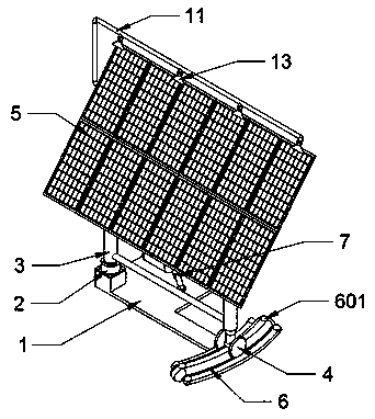
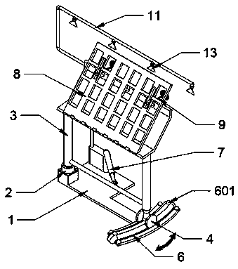
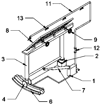
[0030] as attached figure 1 to attach Figure 8 Shown:

[0031] The invention provides a photovoltaic group adjustment mechanism for electric new energy charging piles, including a base 1, a bearing group 2, a support frame 3, a track support wheel 4, a photovoltaic power generation panel 5, a track 6, a stopper 601, and an electric telescopic rod 7 , a photovoltaic assembly frame 8, a threaded adjustment rod 9, a threaded connection column 10, a water supply pipe 11, a solenoid valve 12 and a fan nozzle 13; the bottom of the base 1 is installed on the ground, and the bearing group 2 is installed on the top of the base 1; The left and right ends of the bottom of the support frame 3 are respecti...


PUM


Abstract

The invention provides a photovoltaic group adjustment mechanism matching an electric power new-energy charging pile. The photovoltaic group adjustment mechanism comprises a solenoid valve and sector-shaped nozzles, the bottom of a pedestal is mounted on the ground, and a bearing group is mounted in the top of the pedestal; the left and right ends of the bottom of a bracing frame are mounted on the bearing group and a track supporting wheel respectively; a photovoltaic generating panel is mounted on a photovoltaic assembly rack via screws, and is connected with an external power transmission line via a power line; the inner-side end surface of the track is connected with the right end of the pedestal, and the track supporting wheel is positioned in the top of a track; and threaded adjusting rods are mounted in the top of the bracing frame. The mechanism can adjust the orientation of the photovoltaic generating panel in the top of the mechanism according to the position of the sun, thephotovoltaic generating panel can be orientated to the sun more accurately, and the power generation efficiency of the photovoltaic generating panel is improved; and the bearing group is used cooperatively to fix the bottom of the mechanism during rotational adjustment of the mechanism, and the mechanism is kept stable during rotation.

Description

technical field [0001] The invention belongs to the technical field of photovoltaic group adjustment, and more specifically relates to a photovoltaic group adjustment mechanism for electric new energy charging piles. Background technique [0002] Photovoltaic power generation is a power generation technology that directly converts solar energy into electrical energy by using the photovoltaic effect at the semiconductor interface. At present, photovoltaic power generation has been widely concerned by countries all over the world, and has developed into a new industry. [0003] The inventors found that there is an existing similar photovoltaic group adjustment mechanism, such as a photovoltaic module adjustment mechanism mentioned in patent application number 201721018319.2, which includes a bottom plate, a rotating column, gear one, gear two, a carrier plate, a connecting rod, and an indicator rod As well as the protractor, the rotating column is assembled in the middle of t...

Claims


Application Information

Patent Timeline
Patent Type & Authority Applications(China)
IPC IPC(8): H02S20/30H02S40/10F24S30/425
CPCF24S30/425H02S20/30H02S40/10Y02E10/47Y02E10/50
Inventor 赵瑞霞
Owner 赵瑞霞
Why Eureka
Try Eureka