Digital timer topological structure and control method thereof

A topology and timer technology, applied in instruments, analog-to-digital conversion, signal transmission systems, etc., can solve the problem of inability to meet the large-scale requirements of accelerometers, affecting the application field of I/F conversion circuits, and inability to design I/F circuits Need to adjust and other issues to achieve the effect of reducing power, improving loop response speed, and increasing range

Active Publication Date: 2019-08-02
XIAN MICROELECTRONICS TECH INST
View PDF7 Cites 0 Cited by
  • Summary
  • Abstract
  • Description
  • Claims
  • Application Information

AI Technical Summary

Problems solved by technology

Therefore, the timing time is fixed at one clock cycle CP, which cannot be adjusted according to the needs of I / F circuit design.
[0006]2. The conversion range is too small to meet the large range requirements of the accelerometer
[0008]3. The power consumption of the circuit is large, and the use environment is limited
[0009]Because the working range of the traditional I / F conversion circuit can only be half of the constant current source, in order to increase the conversion range, the output current of the constant current source must be increased, so This leads to a substantial increase in power consumption of the I / F conversion circuit, which in turn affects the application field of the I / F conversion circuit

Method used


Image

  • Digital timer topological structure and control method thereof
  • Digital timer topological structure and control method thereof
  • Digital timer topological structure and control method thereof

Examples


Embodiment Construction

[0031] In order to more clearly illustrate the technical solutions in the embodiments of the present invention, the drawings that need to be used in the description of the embodiments will be briefly introduced below. Obviously, the drawings in the following description are only some embodiments of the present invention. For those skilled in the art, other drawings can also be obtained based on these drawings without creative effort.

[0032] In order to make the object, technical solution and advantages of the present invention more clear, the specific implementation of the present invention will be further described below in conjunction with the drawings and embodiments, which are explanations of the present invention rather than limitations.

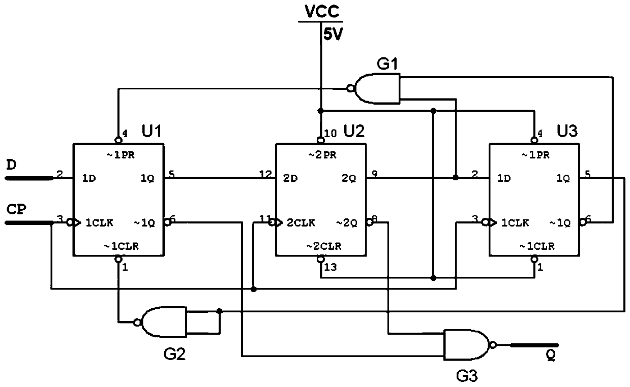
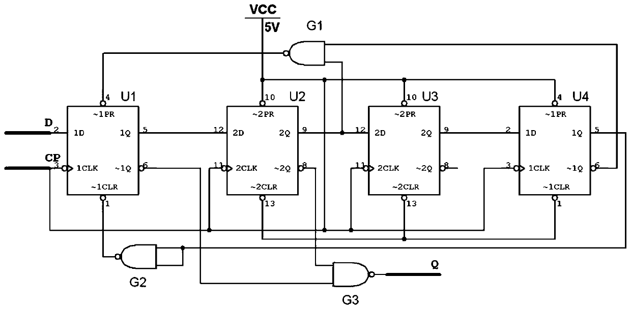
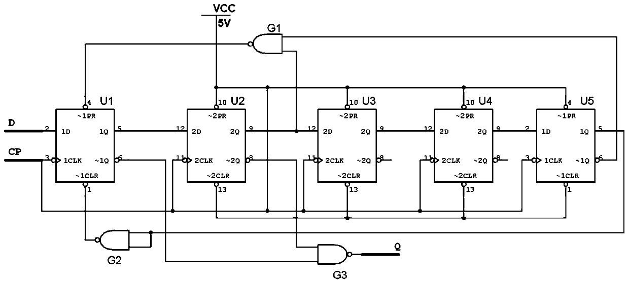
[0033] Such as Figure 1 to Figure 5 As shown, a digital timer topology of the present invention includes a plurality of D flip-flops Un, NAND gate G1, NAND gate G2 and NAND gate G3;

[0034] The clock signal input terminals of multi...


PUM


Abstract

The invention discloses a digital timer topological structure and a control method thereof. The topological structure comprises a plurality of D triggers, a NAND gate G1, a NAND gate G2 and a NAND gate G3. The output end of the NAND gate G2 is connected with the reset end of the first D trigger U1; the control end of the first D trigger U1 is connected with the output end of the NOT gate G1, the first input end of the NOT gate G1 is connected with the anti-phase output end of the last D trigger, and the second input end of the NOT gate G1 is connected with the in-phase output end of the secondD trigger U2; the control ends of the second D trigger U2 to the last D trigger are connected with the VDD end; the first input end of the NAND gate G3 is connected with the anti-phase output end ofthe first D trigger U1, and the second input end of the NAND gate G3 is connected with the anti-phase output end of the second D trigger U2. When the timer is applied to an I / F conversion circuit, thelinearity of an I / F conversion circuit is obviously improved, the power consumption of the circuit is reduced, and the conversion range of the circuit is increased.

Description

technical field [0001] The invention relates to the technical field of digital conversion circuits, in particular to a digital timer topology and a control method thereof. Background technique [0002] The current / frequency conversion (I / F) circuit is a conversion circuit that digitizes the current signal. It is often used in navigation control systems to convert the output current of the accelerometer into pulse output or other occasions that require high-precision analog / digital conversion. Since the output of the accelerometer head is a current analog signal, it must be converted into a digital signal through the I / F circuit before it can be processed by the computer in the inertial navigation system. Therefore, the actual measurement accuracy of the accelerometer is the combination of the accelerometer head and the I / F circuit. Accuracy, only by providing the accuracy of the I / F circuit can the accuracy of the output information of the accelerometer be maintained. The d...

Claims


Application Information

Patent Timeline
Patent Type & Authority Applications(China)
IPC IPC(8): H03M1/50
CPCH03M1/50
Inventor 黄征郭文娟姚景梅尹号
Owner XIAN MICROELECTRONICS TECH INST
Why Eureka
Try Eureka