Lance tube

A spray gun and ring-shaped technology, applied in the direction of furnace, furnace type, charge manipulation, etc., can solve the problems of expensive and difficult welding, achieve the effect of improving force distribution, ensuring corrosion resistance, and increasing the interface area

Active Publication Date: 2019-08-02
SANDVIK INTELLECTUAL PROPERTY AB
View PDF4 Cites 0 Cited by
  • Summary
  • Abstract
  • Description
  • Claims
  • Application Information

AI Technical Summary

Problems solved by technology

However, FeCrAl alloys, in addition to being relatively expensive, are brittle at low temperatures and are also difficult to weld

Method used


Image

  • Lance tube
  • Lance tube
  • Lance tube

Examples


Embodiment Construction

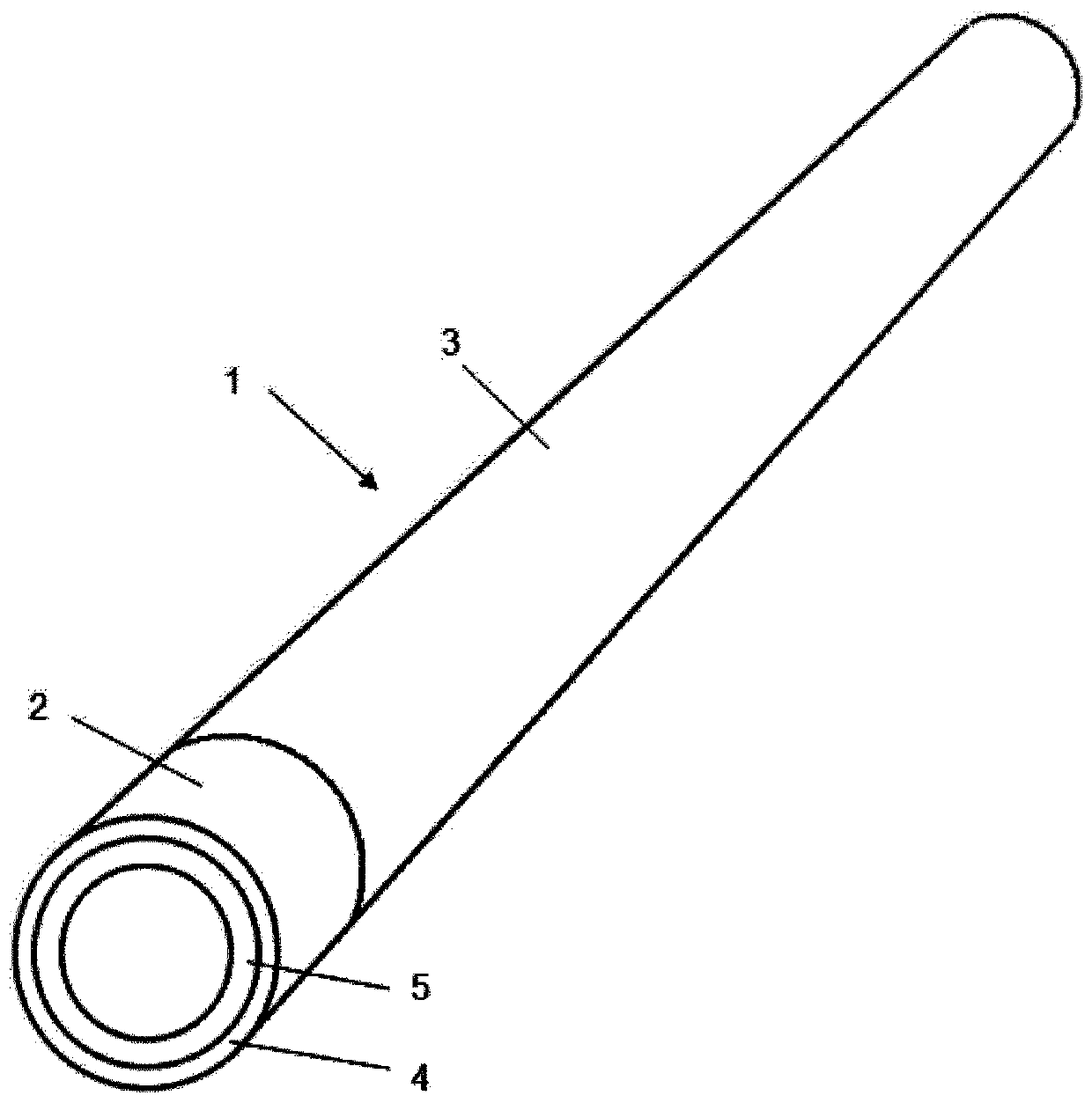
[0040] figure 1 A spray gun barrel 1 according to an embodiment of the present disclosure is shown schematically and not to scale. The lance barrel has a relatively short double-layered end portion 2 and a single-layered main portion 3 . The double-layered end portion 2 has an annular outer layer 4 made of a first alloy and an annular inner layer 5 made of a second alloy. The single-layer main part 3 is formed entirely of the second alloy forming the inner layer 5 of the double-layer end part 2 .

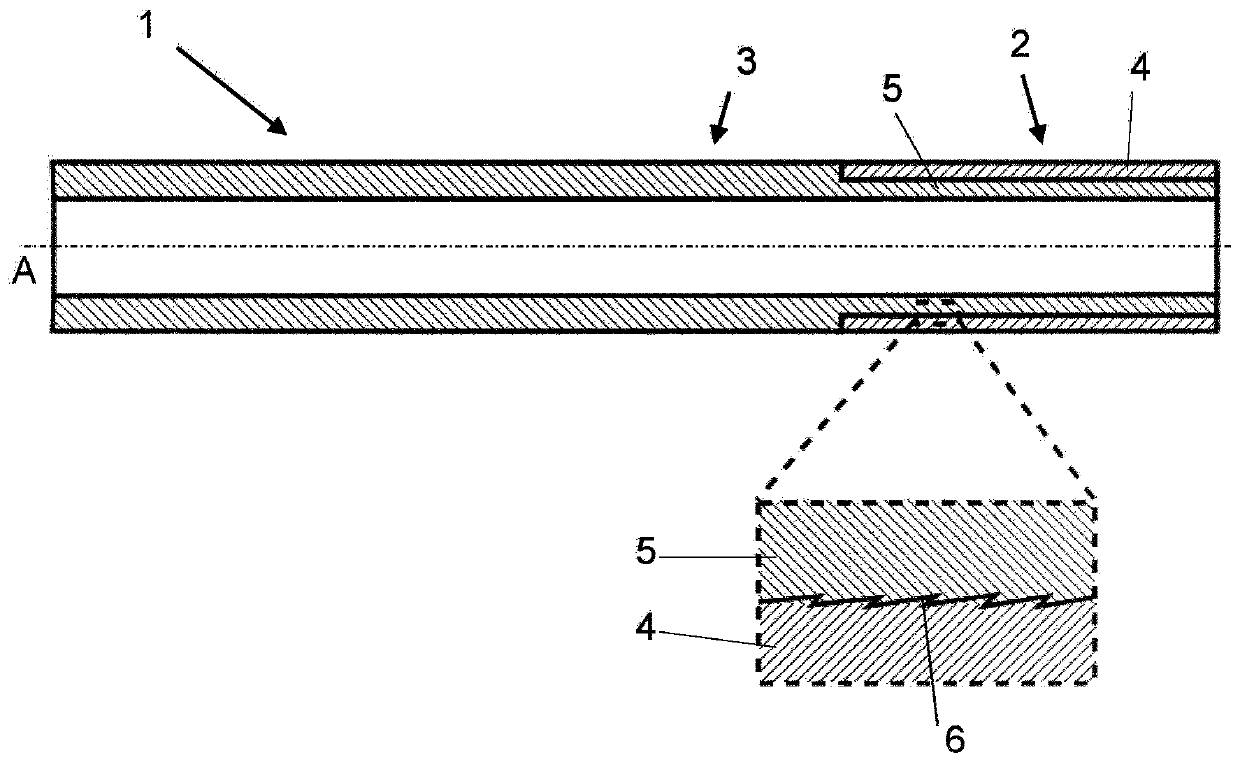
[0041] figure 2 A straight lance tube 1 is shown schematically in a section taken along its longitudinal axis A. It can be seen from the enlarged view of the marked area that the helically extending thread 6 runs in the interface between the annular outer layer 4 and the annular inner layer 5 . A helically extending thread 6 serves to mechanically interlock the two layers 4 , 5 . However, the layers 4, 5 are also joined by a metallic bond formed in the interface by thermal pro...


PUM

PropertyMeasurementUnit
lengthaaaaaaaaaa
lengthaaaaaaaaaa
thicknessaaaaaaaaaa

Abstract

The disclosure relates to a lance tube (1) having a central through-hole extending along a longitudinal axis (A). The lance tube has a double-layered end portion (2) having an annular outer layer (4)of a high temperature corrosion resistant first alloy and an annular inner layer (5) of a second alloy, wherein the inner layer and the outer layer are mechanically interlocked, and wherein a metallicbond has been formed between the inner layer and the outer layer by means of hot working, and a mono-layered main portion (3) of the second alloy. The lance tube is suitable for use in a lime kiln.

Description

technical field [0001] The present disclosure relates to a lance tube according to the preamble of claim 1 . In particular, but not exclusively, the present disclosure relates to a lance tube intended for use in a lime kiln. The lance tube may also be intended for coal dust injection into the lance of a blast furnace, for example. Background technique [0002] In the production of quicklime (calcium oxide) from limestone (calcium carbonate), lime kilns are used in the calcination process. The most commonly used lime kiln is the Parallel Flow Regenerative (PFR) shaft kiln, which consists of two vertical shafts and a connecting cross channel. While the limestone is being calcined in the combustion zone in one of the shafts, the other shaft preheats the limestone. Hot combustion gases are transferred from the calcining shaft through cross channels to the non-calcining shaft where they preheat the limestone located in the upper region of the shaft. The flow direction of the ...

Claims


Application Information

Patent Timeline
Patent Type & Authority Applications(China)
IPC IPC(8): F27B1/02F27B1/16F27B1/20F27D3/16F27D3/18C21C5/46
CPCC21C5/4606F27B1/02F27B1/16F27B1/20F27D3/16F27D3/18F27D2003/169F27D2003/185F27D2099/0036
Inventor 奥勒·埃里克松亨里克·哈尔
Owner SANDVIK INTELLECTUAL PROPERTY AB
Why Eureka
Try Eureka