Metal tube automatic iron wire binding machine

A metal tube and strapping machine technology, which is applied to the parts of strapping machines, strapping objects, and strapping materials, etc., can solve the problems of high machine price, low tightness of metal threading tubes, and easy slipping of tubes, etc., to reduce worker labor Strength, strong and reliable binding, labor cost saving effect

Pending Publication Date: 2019-08-06
隋振
View PDF0 Cites 8 Cited by
  • Summary
  • Abstract
  • Description
  • Claims
  • Application Information

AI Technical Summary

Problems solved by technology

[0004] The automatic tape strapping machine uses adhesive tape to bind the bundled metal threading pipe with low tightness, which is more suitable for non-metallic pipes such as plastic pipes, and the pipes bundled with tape are easy to wear and break during the handling process, causing great harm to customers. big trouble
[0005] The packing tape used by the automatic packing tape strapping machine is used to bind metal threading pipes. The same degree of tightness is low, which is more suitable for objects with elastic surfaces such as cartons and non-metallic materials, and the pipes bundled by packing tape are easy to slip during transportation and handling. out, resulting in dangerous accidents;
[0006] The automatic steel strapping machine is a large-scale and heavy-duty equipment, suitable for large-scale pipes and special-shaped pipes, and has the disadvantages of high machine price, large workshop area, and slow efficiency;
[0007] Therefore, the above-mentioned binding machines are not suitable for binding metal threading pipes.

Method used


Image

  • Metal tube automatic iron wire binding machine
  • Metal tube automatic iron wire binding machine
  • Metal tube automatic iron wire binding machine

Examples


Embodiment Construction

[0031] The present invention will be further described below in conjunction with the accompanying drawings. It should be noted that this embodiment is based on the technical solution, and provides detailed implementation and specific operation process, but the protection scope of the present invention is not limited to the present invention. Example.

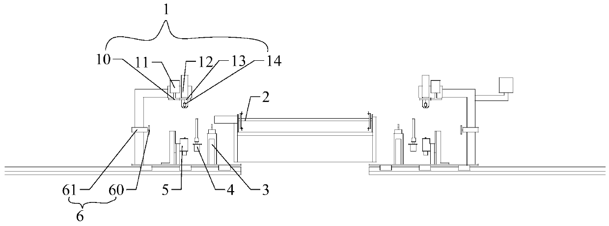
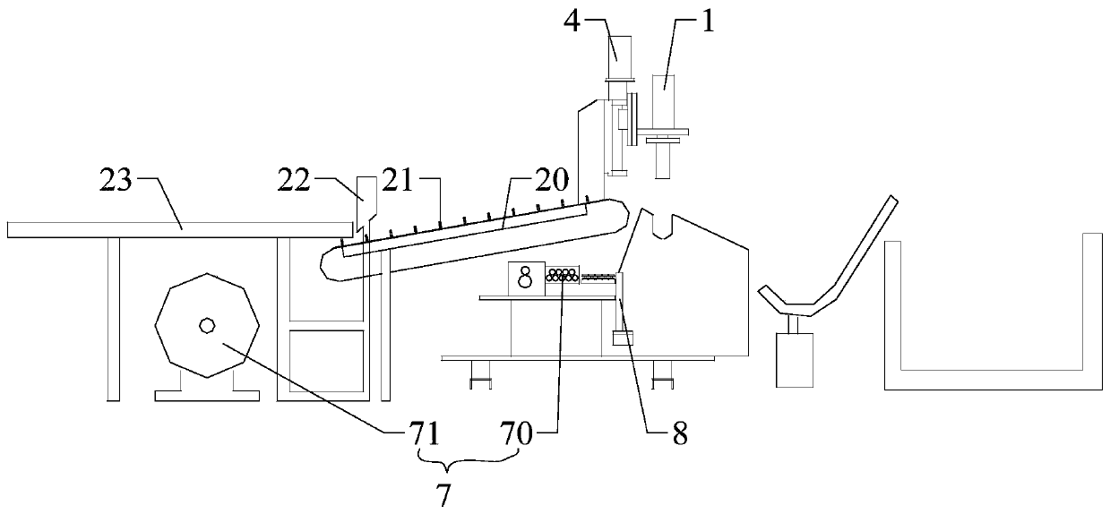
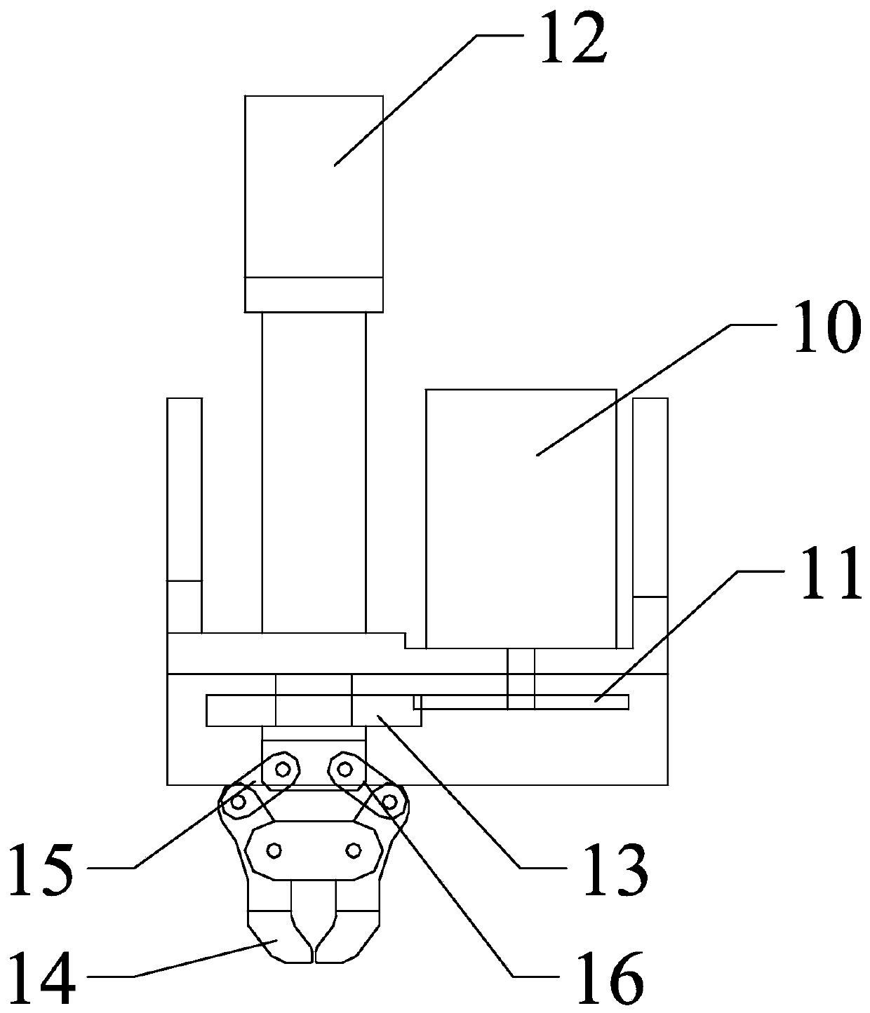
[0032] figure 1 It is the front view of a metal tube automatic wire binding machine according to the embodiment of the present invention, figure 2 It is a side view of a metal pipe automatic wire binding machine according to an embodiment of the present invention, image 3 It is a schematic structural diagram of a wire twisting mechanism of an automatic iron wire binding machine for metal pipes according to an embodiment of the present invention, Figure 4 It is a schematic structural diagram of the unloading mechanism of a metal tube automatic wire binding machine according to an embodiment of the present invention, Figure...


PUM


Abstract

The invention discloses a metal tube automatic iron wire binding machine. The metal tube automatic iron wire binding machine comprises a control cabinet, a metal tube conveying and counting unit and bundling units arranged on the two sides of the output end of the metal tube conveying and counting unit, each bundling unit comprises a shell, a tube holding mechanism, a wire feeding and straightening mechanism, a wire shearing mechanism, a wire holding mechanism and a screw screwing mechanism, wherein the tube holding mechanism is used for holding at least two metal tubes into a metal tube set,the wire holding mechanism is used for tightly holding the binding wire to the outer side of the metal tube set, the wire screwing mechanism is used for tightening the binding wire, the wire feeding and straightening mechanism, the wire shearing mechanism and the wire holding mechanism are arranged in sequence along the conveying direction of the binding wire, the screw screwing mechanism is arranged above the wire holding mechanism, the wire holding mechanism and the tube holding mechanism are located on the same horizontal line, and the tube holding mechanism is located at an output end of the metal tube conveying and counting unit. By adopting the metal tube automatic iron wire binding machine with the structure, automatic feeding, counting, bundling and discharging can be realized, sothat the bundling efficiency is improved, the labor cost is saved, the labor intensity of workers is reduced, the occupied area is small, and the bundling is firm and reliable.

Description

technical field [0001] The invention relates to a metal threading pipe bundling technology, in particular to an automatic wire bundling machine for metal pipes. Background technique [0002] Most of the existing manufacturers use manual binding of metal pipes. Since the length of the pipes ranges from 3 meters to 6 meters, two workers are required at both ends of each metal pipe conveyor to bind the two ends of the metal pipes separately. During this process, two people need to count the metal tubes at the same time. After reaching the set number, manually twist the binding iron wires to achieve bundling, which requires a lot of manpower, low work efficiency, and high labor intensity. Double binding iron wires with a diameter of 1.6 mm is a waste of resources. [0003] Existing strapping machines on the market, such as automatic tape strapping machines, automatic strapping strapping machines and automatic steel strapping machines, are not suitable for strapping metal pipes ...

Claims


Application Information

Patent Timeline
IPC IPC(8): B65B27/10B65B13/18B65B13/20B65B13/16B65B13/28
CPCB65B27/10B65B13/185B65B13/20B65B13/16B65B13/28
Inventor 隋振宁志同隋雷
Owner 隋振
Why Eureka
Try Eureka