Underwater equipment installation and delivery base station

A technology for underwater equipment and base stations, which is applied in the field of underwater equipment installation and delivery of base stations, can solve the problems of high water flow speed, complex flow field of shield wells, and rotation, and achieve the effect of maintaining stability.

Pending Publication Date: 2019-08-06
LINGDONG NUCLEAR POWER +4
View PDF6 Cites 2 Cited by
  • Summary
  • Abstract
  • Description
  • Claims
  • Application Information

AI Technical Summary

Problems solved by technology

Existing hanging baskets and spreaders for equipment delivery are generally used in still water or anhydrous conditions. However, due to the deep water level of the shield well, the water flow velocity in the water intake tunnel 300 and the shield well is high, and the shield The flow field in the well is complex. If the monitoring robot is hoisted directly to the bottom of the shield well using the existing spreader, it is easy to overturn, deflect, and spin, and it is difficult for the monitoring robot to enter the water intake tunnel 300 for monitoring operations.

Method used


Image

  • Underwater equipment installation and delivery base station
  • Underwater equipment installation and delivery base station
  • Underwater equipment installation and delivery base station

Examples


Embodiment Construction

[0049] In order to describe the technical content and structural features of the present invention in detail, further description will be given below in conjunction with the implementation and accompanying drawings.

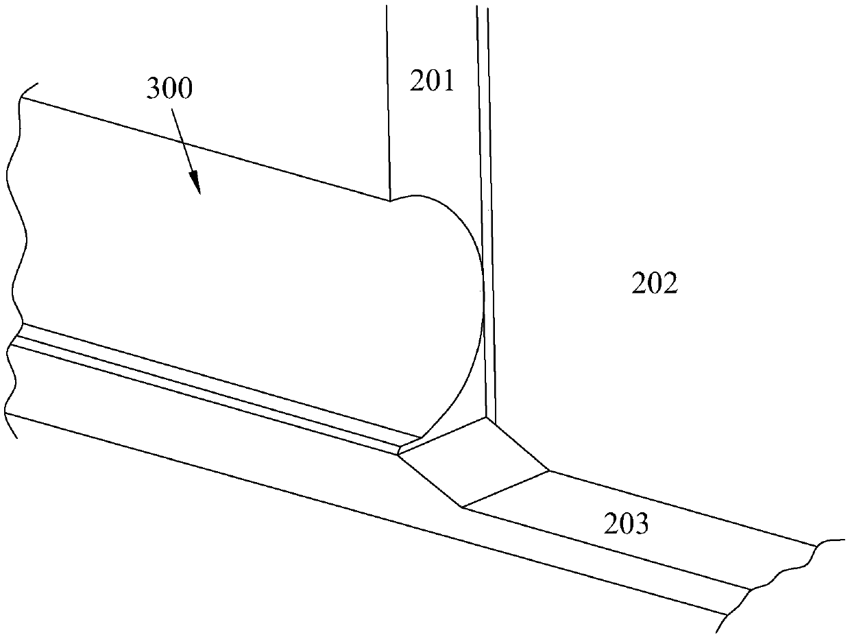
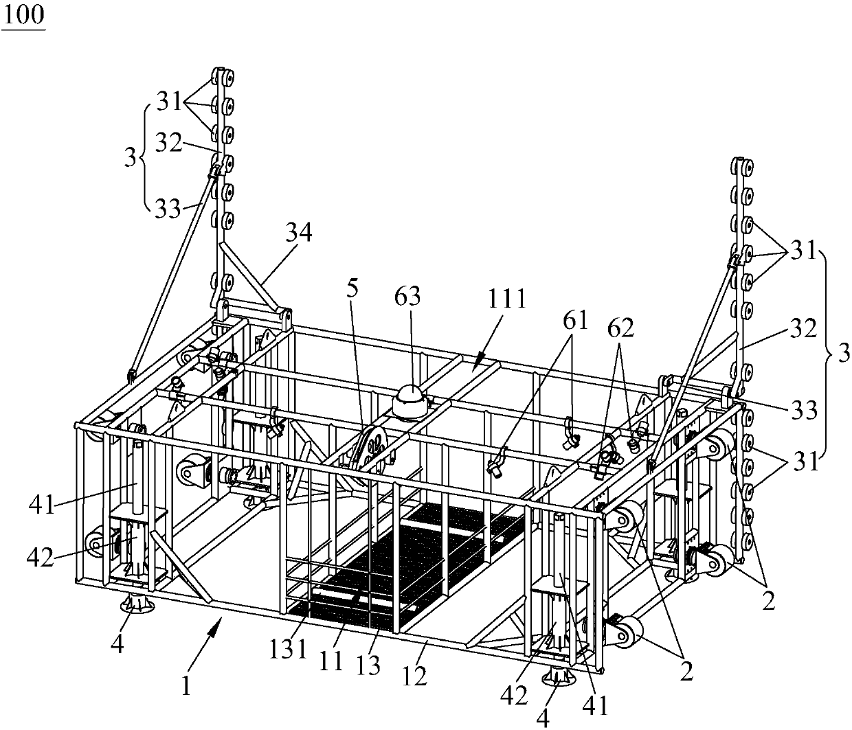
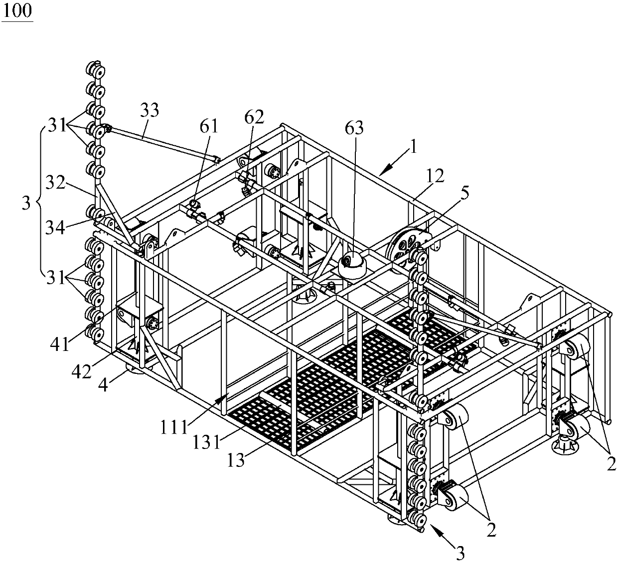
[0050] see Figure 2 to Figure 5, the present invention provides an underwater equipment installation and release base station (hereinafter referred to as the base station) 100, which is used for launching and recovering underwater equipment in shafts such as shield wells. The base station 100 includes a main frame 1 and an adaptive guiding device 2 disposed on the main frame 1, wherein the main frame 1 serves as the skeleton of the base station 100, is the installation basis for the adaptive guiding device 2 and other modules, and is the carrier body of the entire base station 100. Mounting interfaces for various other modules are provided. The main body frame 1 is provided with a cabin 11 for accommodating underwater equipment, and the cabin 11 has an opening ...


PUM


Abstract

The invention provides an underwater equipment installation and delivery base station. The underwater equipment installation and delivery base station comprises a main body frame and a self-adaptive guide device arranged on the main body frame, wherein a cabin for accommodating underwater equipment is arranged in the main body frame; the cabin is provided with an opening for underwater equipment to enter and exit; the self-adaptive guide device comprises a first guide wheel, an elastic piece and a sliding piece capable of sliding relative to the main body frame, wherein the first guide wheel is arranged on the sliding piece and located on the side face of the main body frame, and the elastic piece provides elastic force enabling the sliding piece to slide out of the main body frame. With the first guide wheel sliding along the inner wall surface of a shield well, the underwater equipment installation and delivery base station can maintain attaching to the inner wall surface, and the inner wall surface provides support for the base station, so that the base station can be kept in a stable posture under the action of water flow, and tipping and deflection are avoided. In addition, the first guide wheel abuts against the inner wall surface to drive the sliding piece to slide, so that the base station has the advantage of being self-adaptive to the actual width of the shield well.

Description

technical field [0001] The invention relates to the technical field of mechanical engineering, in particular to a base station for installation and delivery of underwater equipment. Background technique [0002] During the operation and use of the water intake tunnel of the nuclear power plant, there will be marine organisms, sand, silt and other accumulations inside. The adhesion of marine organisms and sediment deposition will affect the water flow capacity of the intake tunnel. Monitor. [0003] There are shield wells at both ends of the tunnel, among which the shield wells suitable for monitoring the entry and exit of robots are as follows: figure 1 As shown, the shield well has a shield well front wall 201, a shield well side wall 202, and a shield well bottom 203. The entrance of the water intake tunnel 300 is located at the bottom of the front wall 201. Enter the water intake tunnel 300 from the entrance. Existing hanging baskets and spreaders for equipment deliver...

Claims


Application Information

Patent Timeline
Patent Type & Authority Applications(China)
IPC IPC(8): B66C1/22B66C13/06
CPCB66C1/22B66C13/06
Inventor 王国河巴金玉邓志燕王华刚李兵刘帅余冰张美玲吴玉陈少南吴凤岐李科李海阳陈智
Owner LINGDONG NUCLEAR POWER
Why Eureka
Try Eureka