Hydrodynamic foaming system and foaming method and closestool comprising foaming system

A foaming system and hydrodynamic technology, applied in the field of sanitary ware, can solve the problems of inaccurate proportioning of foaming agent and water, affecting the number of times of foaming agent use, high foaming agent viscosity, etc., to achieve The effect of improving safety and reliability, convenient operation and simplification of structure

Pending Publication Date: 2019-08-06
河北态及环保科技有限公司
View PDF0 Cites 3 Cited by
  • Summary
  • Abstract
  • Description
  • Claims
  • Application Information

AI Technical Summary

Problems solved by technology

These existing structures will result in inaccurate and unreasonable proportions of foaming agent and water, and require high viscosity of the foaming agent
In addition, changes in the external ambient temperature directly affect the number of times the foaming agent is used, resulting in unsatisfactory foaming effects
[0004] This shows that above-mentioned existing foaming system obviously still has inconvenience and defect in structure and use, and urgently needs to be further improved

Method used


Image

  • Hydrodynamic foaming system and foaming method and closestool comprising foaming system
  • Hydrodynamic foaming system and foaming method and closestool comprising foaming system
  • Hydrodynamic foaming system and foaming method and closestool comprising foaming system

Examples


Embodiment 1

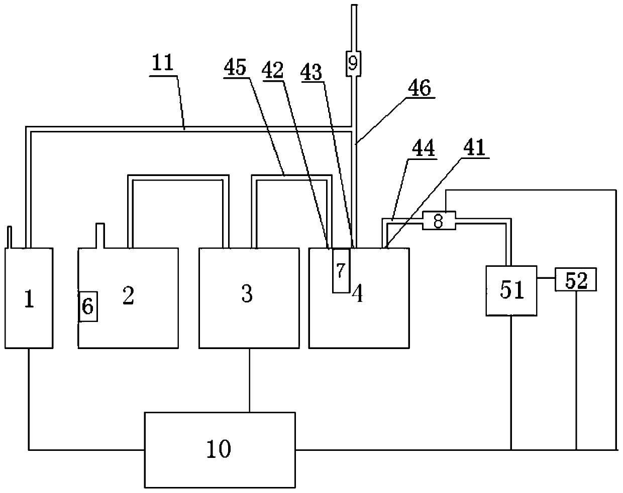
[0037] Reference attached figure 1 As shown, the hydrodynamic foaming system of this embodiment includes a water intake mechanism, a liquid intake mechanism, an air intake mechanism, a hydrodynamic mixing box 4, a foaming tube 9 and a control mechanism 10.

[0038] In this embodiment, the water inlet mechanism adopts a water inlet reversing valve 51 connected with tap water. The water inlet reversing valve 51 is controlled by a solenoid valve 52, and the tap water is directed to the water under the action of the solenoid valve 52 and the water inlet reversing valve 51. The foaming system provides water flow.

[0039] The liquid inlet mechanism includes a liquid storage tank 2 and a liquid pump 3 for pumping out the foaming agent in the liquid storage tank 2. The liquid pump 3 adopts a diaphragm pump, a peristaltic pump, an electromagnetic pump, a centrifugal pump, a gear pump, a vacuum pump, a jet pump, or a stepping motor to accurately extract the amount of foaming agent. In addi...

Embodiment 2

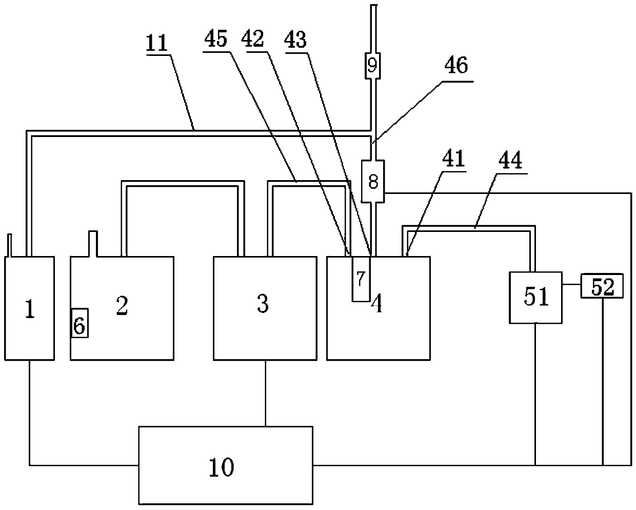
[0052] Reference attached figure 2 As shown, the difference between the hydrodynamic foaming system of this embodiment and the first embodiment is that the vacuum breaker 8 is arranged on the connecting pipe 46 connected to the liquid outlet 43, which also plays a role in avoiding the siphon phenomenon. The remaining parts are the same as the first embodiment, and will not be repeated here.

Embodiment 3

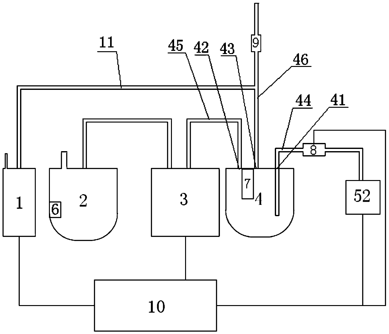
[0054] Reference attached image 3 As shown, the difference between the hydrodynamic foaming system of this embodiment and the first embodiment is that the water inlet mechanism uses a solenoid valve 52 directly connected to tap water, and the control mechanism 10 can directly control the solenoid valve 52 to achieve the The water mechanism transmits the power water flow to the water power mixing box 4, which is simple and reliable.

[0055] In addition, the water outlet end of the water outlet pipe 44 connected to the water inlet 41 of the hydrodynamic mixing tank 4 extends into the lower part of the hydrodynamic mixing tank 4, so that the water with a certain pressure is turned from bottom to top in the tank to reach the power Uniform mixing of foaming agent and water. The liquid outlet end of the liquid outlet pipe 45 connected to the liquid inlet 42 can also be extended into the lower part of the hydrodynamic mixing box 4, which is more conducive to the uniform mixing of foam...


PUM


Abstract

The invention discloses a hydrodynamic foaming system. The system comprises a water inlet mechanism, a liquid inlet mechanism, an air inlet mechanism, a hydrodynamic mixing box, a foaming pipe and a control mechanism; a water inlet and a liquid inlet are formed in the side wall or the top of the hydrodynamic mixing box; a liquid outlet is formed in the top of the hydrodynamic mixing box, the waterinlet is connected with a water outlet pipe of the water inlet mechanism, the liquid inlet is connected with a liquid outlet pipe of the liquid inlet mechanism, the liquid outlet is connected with aninlet of the foaming pipe through a connecting pipe, the connecting pipe further communicates with an air outlet pipe of the air inlet mechanism, and the control mechanism is connected with the waterinlet mechanism, the liquid inlet mechanism and the air inlet mechanism. A closestool and a foaming method are also disclosed. By adding the hydrodynamic mixing box, a foaming agent is injected in advance, and the use amount of the foaming agent is accurately controlled by logically controlling the working time of a liquid pump. The uniformly mixed foaming liquid is mixed with gas by utilizing the pushing force of water to finally generate foam, so that the application range is wide. The system is simple in structure, low in cost, intelligent in control and capable of rapidly generating foamand better meeting the requirements of customers.

Description

Technical field [0001] The invention relates to the technical field of sanitary ware, in particular to a hydrodynamic foaming system and a foaming method, and a toilet including the foaming system. Background technique [0002] With the continuous improvement of people's living standards, the hygienic requirements for toilets have also been increasing. The current toilets generally have shortcomings, and it is difficult to clean the toilets contaminated by dirt. What is especially annoying is that when hands are relieved, dirt and sewage will sometimes be sprayed on the surface of the toilet or on the body, soiling the body and clothing, and the odor of E. coli and other bacteria and excrement will be emitted into the air. Seriously affect indoor air quality and threaten human health. [0003] Although there has been an odor release agent foaming spray system in the toilet in the prior art, the pumping volume of the foaming agent in the existing foaming system is mainly through th...

Claims


Application Information

Patent Timeline
Patent Type & Authority Applications(China)
IPC IPC(8): E03D9/00
CPCE03D9/00E03D9/005
Inventor 闻荣杰陈明杯
Owner 河北态及环保科技有限公司
Why Eureka
Try Eureka